02 August 2020
Ever thought that robotic technology is far out of reach for us mere mortals? Well, take it from me, an ordinary guy with very little professional training on the subject: it really is very easy and I can help you do it yourself too if you are patient enough.
In this article, I am going to explain how you can make your own robot arm using readily available resource materials and very basic tools. What is required on your part is a very basic knowledge of electronics, some understanding of software programming, the ability to acquire the materials that I will soon specify, a bit of creativity and the patience to follow through this article.
As a firm believer of the idea that optimal learning is assured when a mind appreciates what it needs to learn, permit me to invite you to watch a small video that may motivate you to start working on your robot by giving you an idea of how your final contraption may look like.
Video-1
This article's target machine is a robot arm with 5 degrees of independent motion. Figure-1 is an intuitive three dimentional representation of the arm and figure-2 is a 2D model representation of the technical aspects of the robot. The use of "rod-piece-1", "rod-piece-2", the "connector-piece" and the "immovable-piece" takes away one degree of motion about hinge-3.
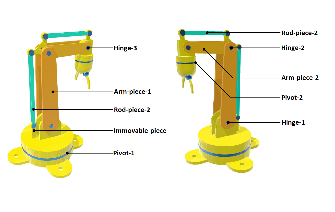
Figure-1 [View fullscreen]
You could of course choose to make your robot have 6 or more degrees of motion depending on the resources available to you. The principles outlined in this article will enable you to find a way to add more degrees of motion to your design.
Now, why did I choose to include rod-piece-1, rod-piece-2, the connector-piece and the immovable-piece into my design? It was because of a lack of sufficient resources at the time of making the robot that I chose to do so. The purpose of incorporating these pieces in the assembly of the arm is to ensure that the hand's orientation is always vertical irrespective of any motion that may be imposed on any part of the arm. Let me explain how that works.
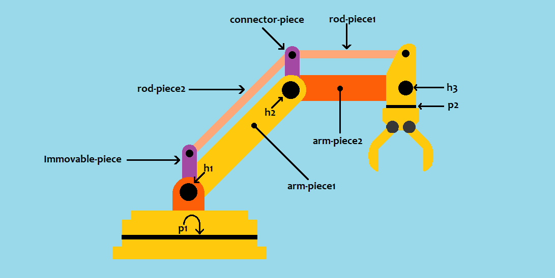
Figure-2
We know from our study of Geometry that the opposite sides of a parallelogram are parallel to each other. A careful consideration of Figure-2 reveals that a combination of the immovable-piece, hinge-1, arm-piece-1, hinge-2, the connector-piece and rod-piece-2 constitute a parallelogram if the lengths of the immovable-piece and the connector-piece are equal and the lengths of arm-piece-1 and rod-piece-2 are equal. Furthermore, if the orientation of the immovable-piece is fixed such that it is always veritical (hence my choice to name it so) by making it one piece with the base of the robot, it follows from the geometric principle about parallelograms that the orientation of the connector-piece will also always be vertical.
In order to allow the connector-piece's orientation to remain vertical at all times while allowing the free and independent movements of arm-piece-1 and arm-piece-2, it is neccessary for the connector-piece to rotate about hinge-2 independently from either arm-piece-1 or arm-piece-2 because as anyone of these arm-pieces rotates about its hinge, its angle with the connector-piece varies. In order to allow this varience, it is neccessary for the connector-piece not to be attached to arm-piece-1 or arm-piece-2.
Suppose the connector-piece was attached to either arm-piece-1 or arm-piece-2 or both, such a configuration would render the angle with anyone of these pieces to be a constant in relation to the connector-piece. Since it is a requirement for anyone of these pieces to move, it is clear then that such a configuration would not work because a constant angle with the connector-piece implies no motion at all with anyone of the arm pieces that maintains a connection with it. It is clear then that unlike the immovable-piece which should be permanently attached to the body of the robot by design, the connector-piece should, by design, be permitted to rotate freely about hinge-2 irrespective of anyone of the motions of arm-piece-1 and arm-piece-2.
Now that we have established that geometric principles dictate that the orientation of the connector-piece is always vertical, looking intently at Figure-2 again reveals once more that a combination of the connector-piece, rod-piece1, the hand, hinge-3, arm-piece-2 and hinge-2 could also constitute a parallelogram if the lengths are adjusted accordingly. Assuming that our design has ensured this, it therefore implies that since the orientation of the immovable piece and the connector-piece are always veritical, the orientation of the hand is similarly always rendered vertical by virtue of it being an opposite side to the connector-piece in a parallelogram.
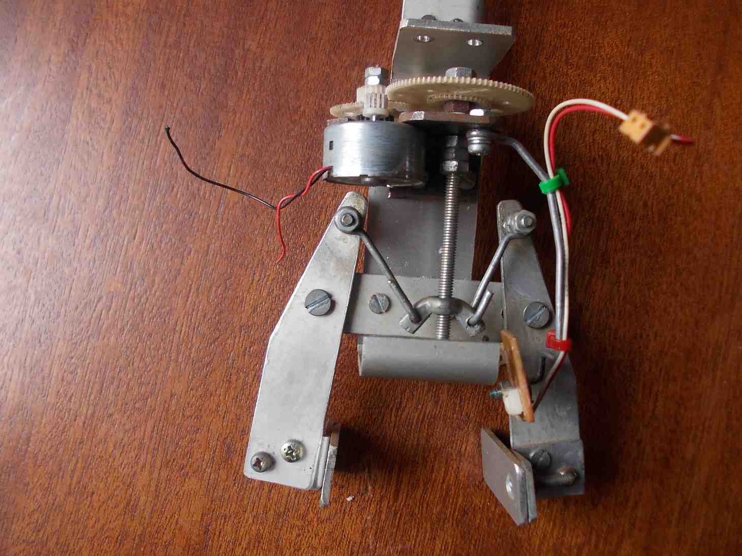
So there it is: by means of this simple geometric trick, we are able to take away the independent motion of the hand about hinge-3 and bind it with the whole arm such that it always maintains a vertical orientation because our poverty demands so. Consider how Figure-1 and Figure-2 compare to the real thing depicted in Figure-3.
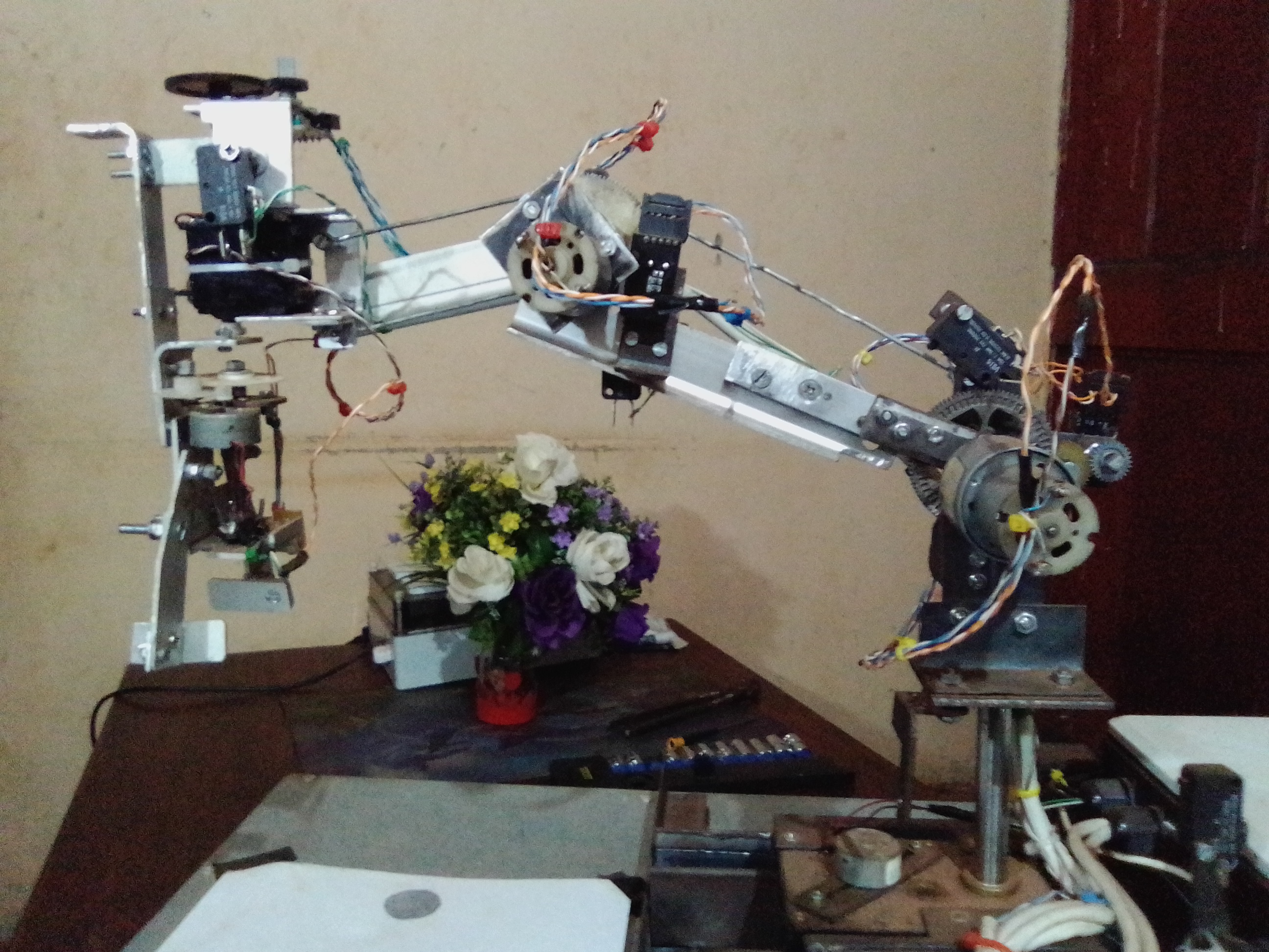
Figure-3
As you can see when you look at the robot that I made, I used geared DC motors for actuators. In case you are wondering why I chose to do so, I will have you know that I would have prefared to use servor motors or even stepper motors for a much greater effeciency than I managed to effect with the geared motor actuators on the robot. Unfortunately, what has gone into the making of the robot is what was available to me at the time of the making of the robot. Also, I must confess at this point that I used a great deal of stuff from my collection of scrap materials hoarded over the years from broken devices.
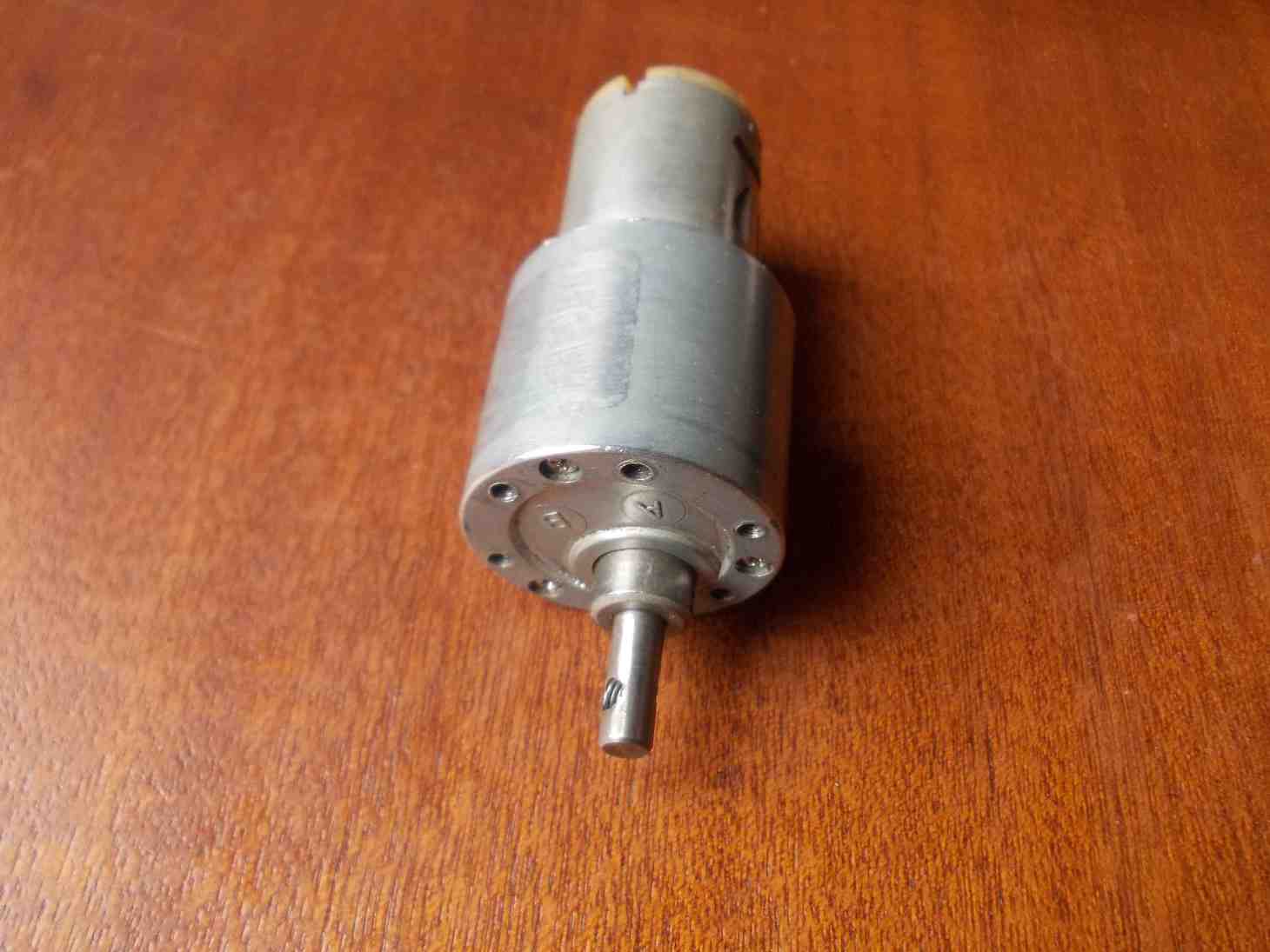
Figure-4
The actuator that does most of the heavy lifting is the one that actuates the entire arm around hinge-1 as shown in Figure-2. The actuator that I selected for this role is shown in Firgure-4 and can deliver 6kg.cm worth of torque according to its datasheet. A similar actuator could be used to actuate arm-piece-2 around hinge-2 or a less powerful one.
Of course, the torque you select for each actuator will very much depend on the lengths of your versions of arm-piece-1 and arm-piece-2 as shown in Figure-2. The lengths for my robot are 180mm (7.1 inch) for arm-piece-1 and 150mm (5.9 inch) for arm-piece-2.
Given more freedom I would have chosen a 25kg.cm servor for actuating the whole arm up and down around hinge-1, an 11kg.cm servor for arm-piece-2 up and down around hinge-2, a 6kg.cm servor for actuating the whole arm clockwise and unticlockwise around pivot-1, a 3kg.cm servor for actuating the hand clockwise and unticlockwise around pivot-2 and a 11kg.cm servor for the hand in order to deliver a very powerful grip.
As it is, I do not know what the maximum torque for actuating the robot arm clockwise or unticlockwise around pivot-1 is because the gearbox that I selected for this function is scrap material without a datasheet and I never took the trouble to measure it myself. My estimates concerning it range from 3kg.cm to 4kg.cm. As for actuating arm-piece-2 around hinge-2, I had to modify an existing gear-box so as to increase its output torque in my project. For this reason once again, I am not too sure how much this actuator really is capable of. My estimates range from 3kg.cm to 4kg.cm in this case as well.
The most mechanicaly challenging piece of the robot is the hand. There are of course many ways to design a mechanical hand that consists of two fingers but I am going to outline two methods that have worked for my project.
The first employs a principle that given a screw and a nut that fit perfectly into each other and if we were to maintain that the nut never spins as we rotate the screw that has been threaded into it as illustrated in Figure-5, the nut would, by virtue of the rotation of the screw, translate across the length of the screw in a certain direction. If the spin of the screw were to be reversed, the direction of the translation of the nut would also be reversed. In this way, we could exploit this principle to convert the circular spin motion of a motor into linear motion.
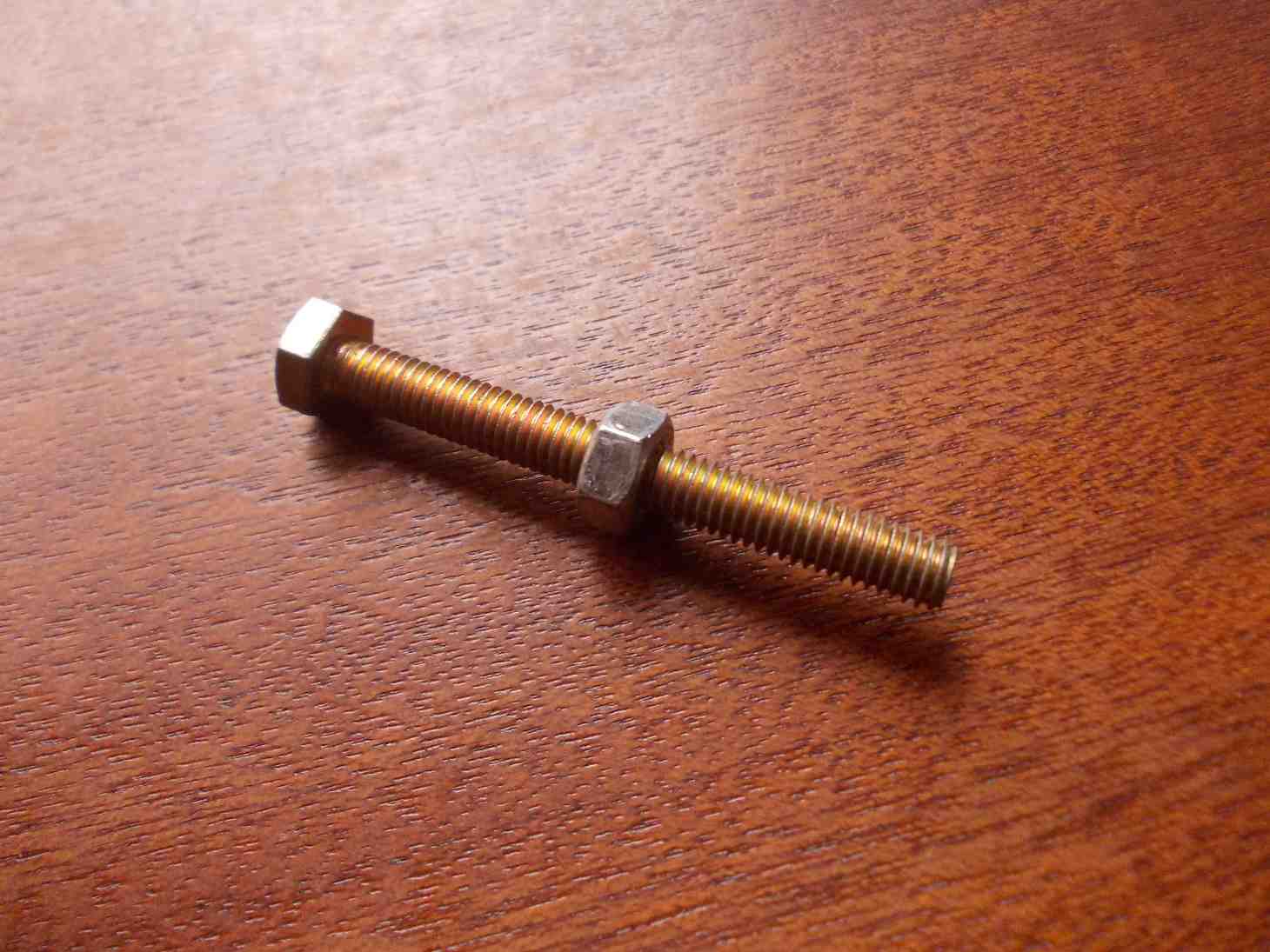
Figure-5
Figure-6 is a representation of this principle in application. Slide-1 is a set of pictures of a real hand that I made for my project in line with the principle explained above. The use of three gears (as shown below) is an attempt to multiply the torque of the motor. You are of course welcome to use more gears in your application in order to increase the grip of your hand if you wish.
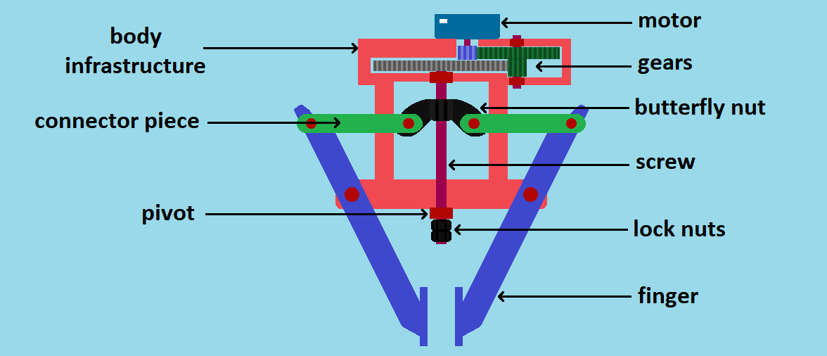
Figure-6
Slide-1
As you can see in Figure-6, I chose to use a butterfly nut as opposed to the kind depicted in Figure-5 because it is easier to drill holes on the wings of the nut so as to use them as hinges that will in turn serve as connection points between the nut and the connector pieces.
How can you fasten a gear to the screw that does the spining? One way that I find very effective is to use nuts as shown in Figure-7. This turns out to be a very effective solution because screws and nuts are readily available and the only headache this technique leaves you with is to find or machine your gear hole to match the diameter of the screw that you may choose to use.
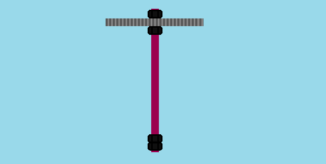
Figure-7
Slide-2
A hand designed based on the screw and nut principle does have a disadvantage. The only disadvantage that I have identified thus far is that as should be expected of such a system, gripping an object results in a locking effect on the part of the butterfly nut and the drive screw. The tendency for bolts and nuts to lock when forced to do so is normally very desirable in engineering. Many applications take advantage of this natural effect. All methods of fastening things using screws and nuts owe their existence to this effect.
Unfortunately, this locking effect is an undesirable side-effect in our application. One way of resolving it is through the use of software. This software based compensation will be discussed more clearly under the softtware section later on in this article but what needs to be done in a nut shell is to set the drive electric power for a grip action always sufficiently smaller than the power used for a release action by the hand.
Another more simpler method that has worked for me has to do with the nature of gears. The hand that we need to build needs to have two fingers that each rotate from each one's fixed hinge in unison with the other such that if one finger rotates in one direction, the other needs to be rotating in the opposite direction at the same speed. To state this more scientifically, the angular velocity and angle of the one finger around some pivot needs to be the additive inverse and mirror image of the other at any moment respectively. If we can device a mechanical means to ensure that this requirement is met with regard to some finger-like rods attached to some gears, we've got ourselves a functional hand.
Animation-1
As it turns out, a gear system arranged as illustrated in Animation-1 produces exactly this desired effect. If we could therefore find a way of attaching fingers on the two gears (as shown in Slide-3) and a way to drive one of the gears by means of a powerful actuator, that would effectively be a hand!
Slide-3
In order for us to successfully automate our robot, it is very important that we find a way to know exactly how much each of the robot arm pieces have moved at any given moment. What I recommend for much greater presicion is the use of stepper motors or servor motors. Stepper motors do not need encoding mechanisms in order to rotate to a desired angle with precision even though the availability of such a feedback system would be advantagous. On the other hand servos possess built-in positioning feeback systems within themselves and therefore make it very easy to rotate a limb-piece with precision. Since I have already undertaken to build the robot using the geared DC motor actuators that need an external encoding system, you will unfortunately have to bear the consequences of my choices at the time of making my robot.
Given the DC geared motor choice, I would further recommend the use of photo-encoders that are normally attached to the back end of the rotor of a motor and which exploit an LED and photo-transitor combination principle in their operation. This method of measuring the motion of a motor is very sensitive and affords much greater precision even given very tiny movements of the motion of the output shaft of a gearbox. I really would have preffered to use these for my project but alas, it has proven very difficult for me to get hold of them and so once again, you will have to put up with explanations pertaining to an inferior but readily available form of technology: the simple encremental encoder.
Even though very sensitive encremental encoders are readily available on the market, they are very expensive. That explains why I chose the KY-040 rotary encoder shown below (Figure-8). This encoder can only deliver 20 pulses per revolution (about 18deg steps) and can handle a maximum rotational speed of 60RPM with accuracy. To be sure, that is highly undesirable for someone who desires some serious level of accuracy but it is good enough to demonstrate the concept. This does of course imply that our robot will have limitations as regards precision but we can be thankful that these encoders do at least afford us some opportunity to measure the various movements of our arm pieces with a small degree of accuracy that still allows us the ability to automate the robot to a reasonable degree.
Figure-8
Given that our target robot needs to have 5 motor-based actuators, 4 encremental encoders (with two pulsating output signals each) and 5 limit switches, it therefore implies that our robot control system will need to accomodate 13 digital inputs (8 taken from the encoders and 5 from the limit switches) and should be able to drive 10 PWM (Pulse Width Modulation) outputs (two for each of the five motors). The hardware that I chose to meet this requirement is the Raspberry Pi B+ model computer. It comes with a 40 pin GPIO hearder and is powerful enough to host a Linux operating system in it. This, in turn, implies that we will have greater freemdom choosing a programing language for the project.
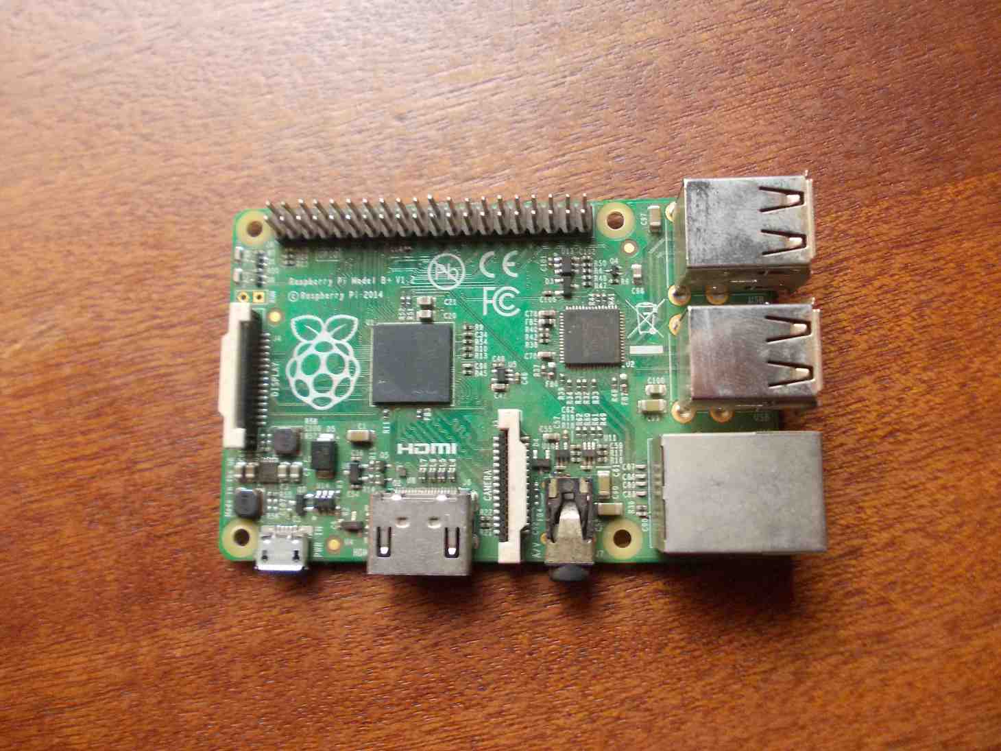
Figure-9
I have also looked into using the NodeMCU as a possible processing unit for the robot and even went as far as writing software to this effect. Unfortunately, I accidentally burned the only unit that I was in possession of before I got to the point of automating the robot based on data acquired from limit switches and encoders. As it is, the extent to which I have written the software for the NodeMCU is such that only manual control of the robot is possible. I have decided to include this code in this article as well and leave it up to you to figure out how you can learn from the full code written for the Raspberry Pi computer to see how you can adapt the half written code for the NodeMCU to produce the same functionality that can be obtained from the Raspberry Pi computer if you wish. Please feel free to give me a ring if you encounter some serious challenges.
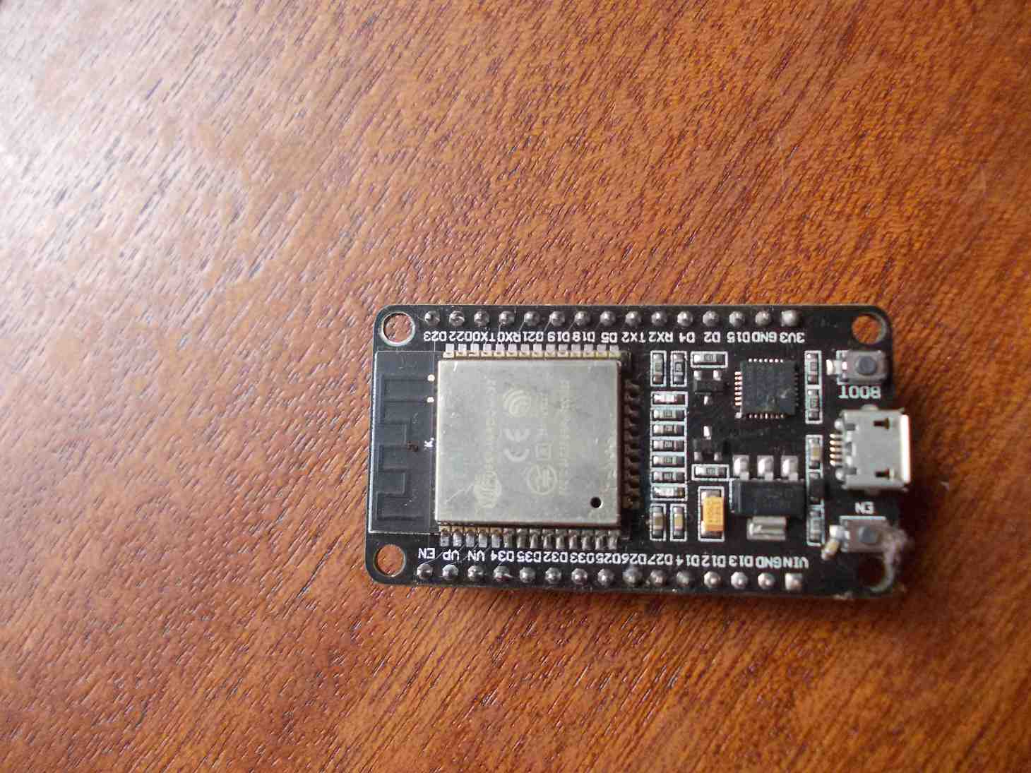
Figure-10
Although 10 independent PWM output signals would be ideal for the project, I was once again serverely restricted by my lack of sufficient electronic components required to build all 5 H-bridge drive circuits for the 5 motors to just 1 H-bridge circuit and therefore 2 PWM signals for all the 5 motors. For this reason, I devised a way to multiplex the only available H-bridge circuit among the 5 motors.
As you may very well expect, this implies that only one motor can be moved in any desired direction at a time and thus further implying that it will not be possible for us to simulate movements similar to those exhibited by animal physiological systems. Also, given the crude accuracy of the encremental encoders chosen for this project implies that we cannot simulate a deceptive trick of making it appear as though several motors are driven at the same time by attempting to repeatedly and sequentially drive each motor within a selected list (chosen for a desired simultaneous make-belief movement) for a very small amount of time and going through the loop over and over until the desired simultaneous make-belief movent has been archieved.
Figure-11 is a block diagram that explains the electronic hardware arrangement for the robot arm. As may be noted from the diagram, the Raspberry Pi outputs a total of 7 signals: two PWM signals for the clockwise and unti-clockwise directional rotations of the motors and the other five are simple binary signals for selecting a target motor that the computer intends to drive. In addition to this, it takes feedback signals from limit switches and encoders associated with each motor.
The PWM signals from the Raspberry Pi computer are fed into the H-bridge circuit that serves to modulate a supply of 12V as outputs that are to be fed into the multiplexing circuit that distributes the modulated 12V supply to a selected motor that the Raspberry Pi computer targets to drive. The selection is made by the Raspberry Pi computer and this thus explains why the multiplexor circuit accepts 5 selector signals from the Raspberry Pi computer as inputs.
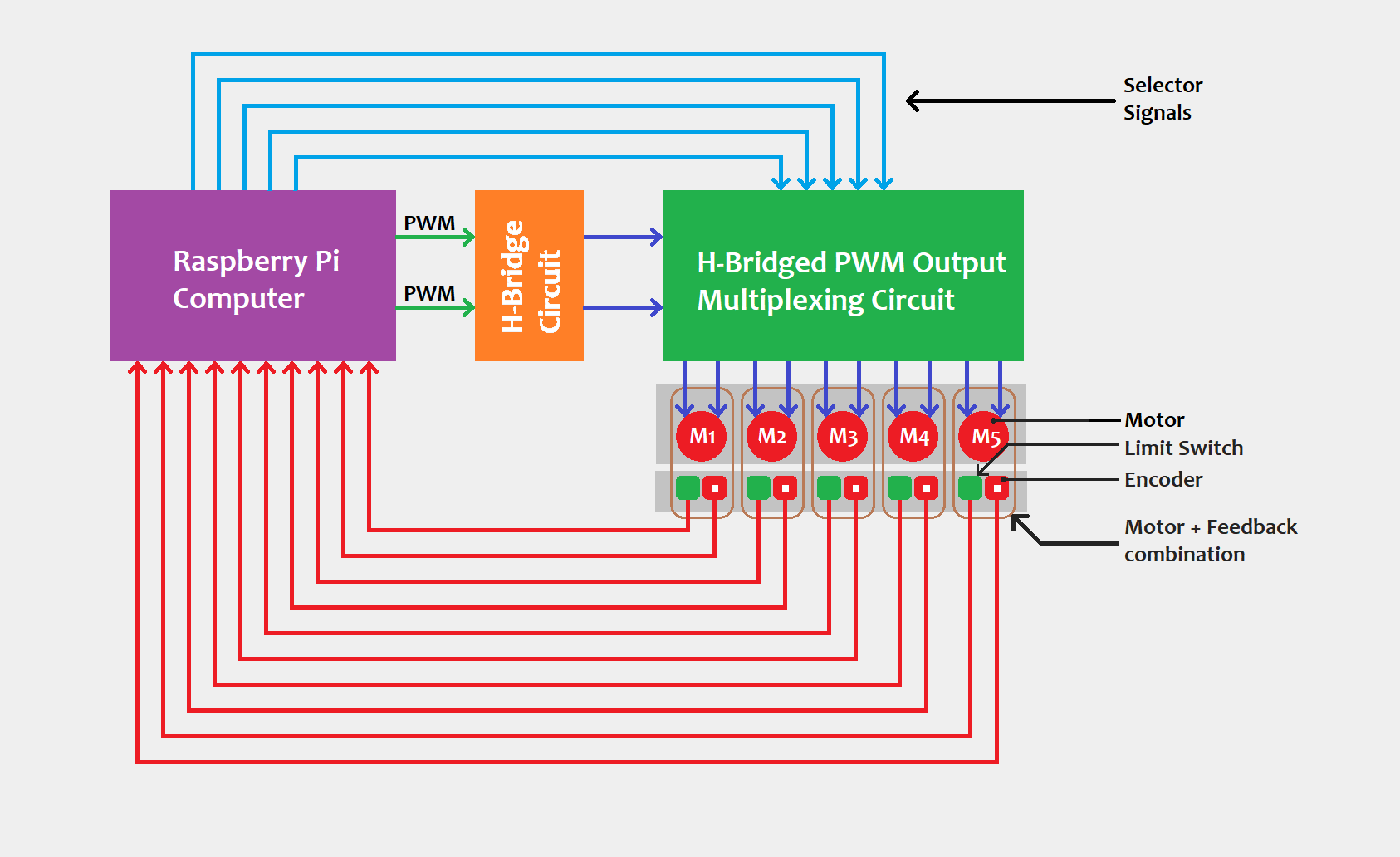
Figure-11
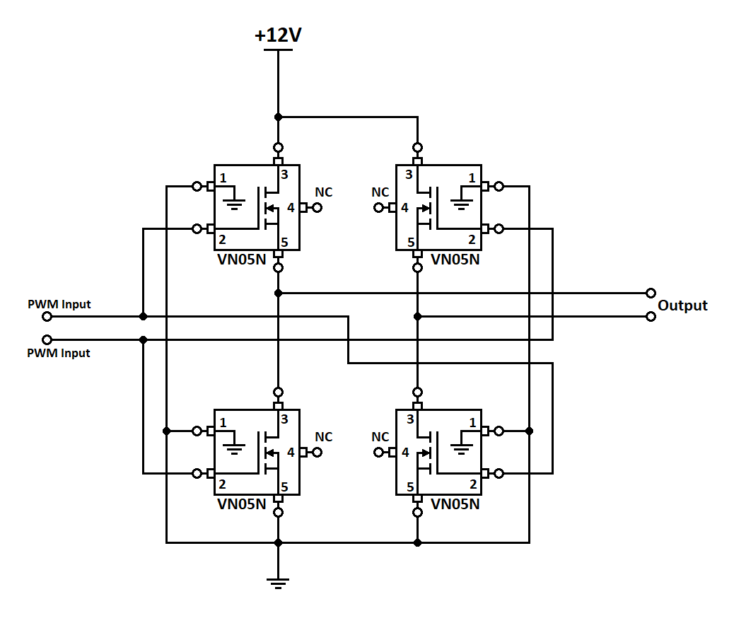
Figure-12
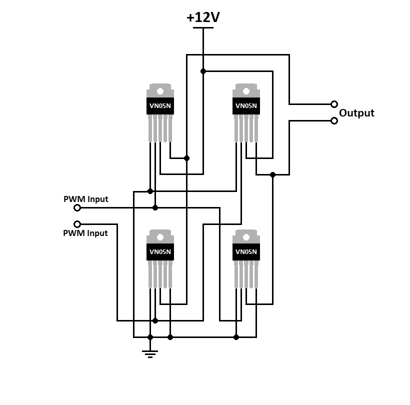
Figure-13
Figure-12 and Figure-13 are equivalent but Figure-11 is much more intuitive. I chose to use the VN05N solid state relay chip for the PWM switching because that was the best choice available to me then. All transistors that were available to me at the time of the making of the robot were such that a very tiny current could flow out through their emmiter pins and were thus not useful in building the lowwer half of an H-bridge circuit. Luckily for me, a lady that I had offered some help with her university project chose to donate a few VN05N solid state relay chips to me some time before the robot project.
Pin 4 of the VN05N chip is actually used for measuring status current on a load using a resistor. The datasheet refers to it as a "status" pin but I chose not to use it and thus refer to it in Figure-12, Figure-13 and others as a 'no-connection' pin.
If you have not already done so, it is worth noting that the gate/base pins (refered to as "input" pins on the VN05N datasheet) of the chips that are situated on the opposite ends of a diagonal line in the H-bridge circuits of both Figure-12 and Figure-13 are connected together with the intention that they should also be activate together by one signal.
A consideration of Figure-14 shows what happens when one of the PWM input lines of the H-bridge circuit is activated. The relay chip at the top left corner will be activated along with the relay chip situated at the bottom right corner. This arrangement then allows a flow of current (in terms of the conventional flow model) in the direction traced by the red line. The direction of flow makes the motor spin in a clockwise direction.
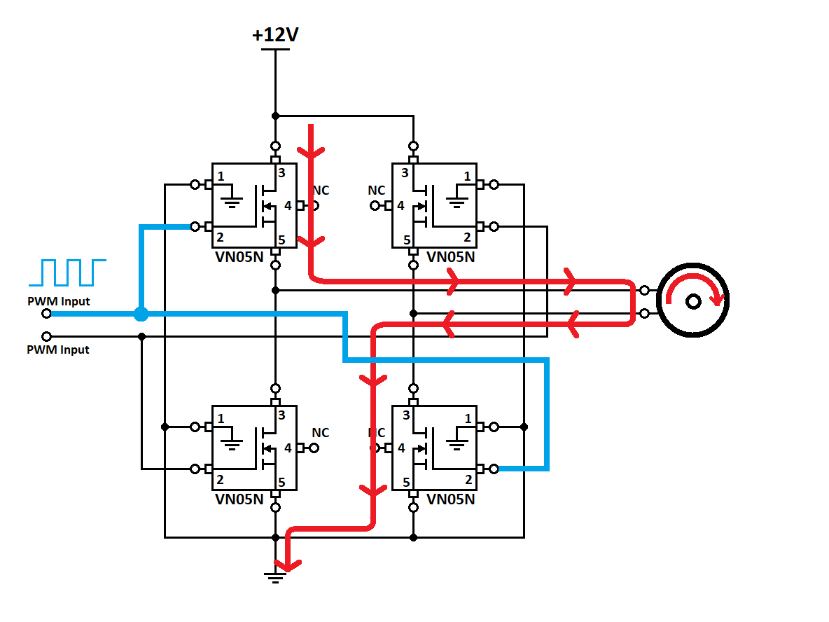
Figure-14
Conversely Figure-15 shows a situation in which the relay chip at the top right corner is activated along with the relay chip situated at the bottom left corner. This arrangement allows a flow of current in the direction traced by the red line. Further, this direction of current flow translates into the motor spining in the unti-clockwise direction.
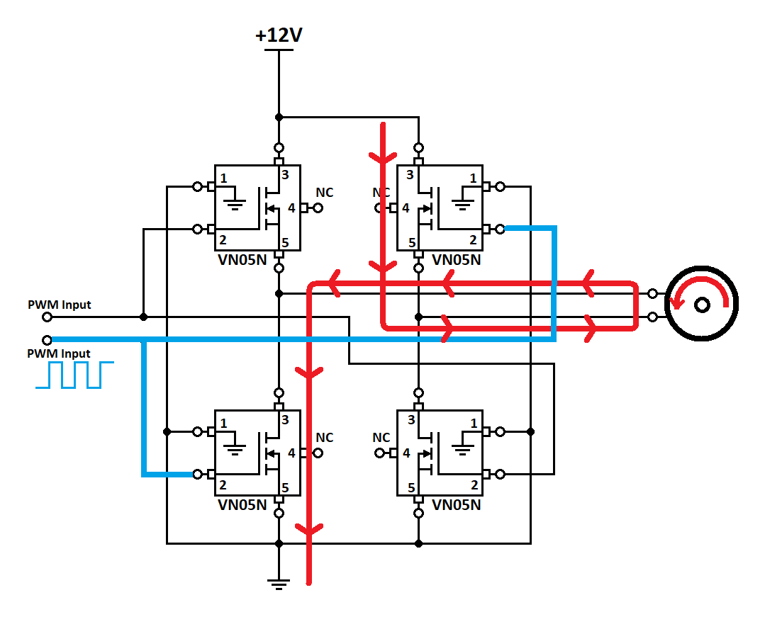
Figure-15
Quite clearly then, we employ an H-bridge circuit for the purpose of manipulating the direction of rotation of a motor. The reason why it is important to use a solid state devices (like a transistor, a solid state relay chip as you have seen in this project etc.) is that these devices can enable us to use PWM to manipulate the speed of a DC motor. Thus, by means of an H-bridge ciruit that is constructed of solid state switching devices, we have the power to control both the speed and direction of the rotation of a motor using just digital signals and control devices. No advanced knowledge of analog electronics is required in this regard.
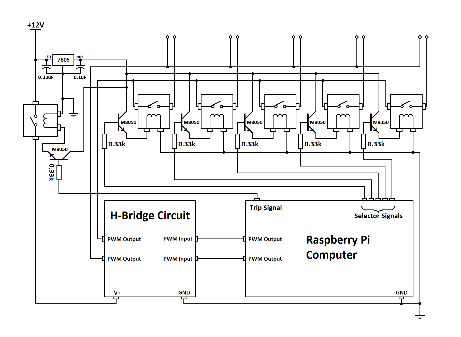
Figure-16 [View fullscreen]
Looking at Figure-16, it should be clear that the function of the multiplexor circuit is to switch among the five motors which one may be connected to the modulated 12V output of the H-bridge circuit. It shuld also be clear that altough selecting more than one motor is possible, it is not always possible to select more than one motor and still retain complete freedom with regard to the choosing of the direction of rotation on each selected motor.
The circuit uses a simple electromechanical 5V relay for switching and each of the 6 relays is activated by the Raspberry Pi computer via a 330ohm resistor and an M8050 NPN transistor. The sixth relay that appears to be out of place (situated at the top left part of Figure-16) is not employed for selecting any of the 5 motors but for tripping the entire multiplexor circuit. This is a security feature designed to protect the robot in the event that a software bug crashes the software driver that controls the hardware while one of the motors was activated. I added this feature later in my project after I learned the importance of including a tripping mechanism the hard way. You do not want to know how many times I broke my actuators' gearboxes before I was humble enough to concede to a trip circuit. Therefore, take my advice and use it right away in your project. Learn from my mistakes.
I will not attempt to walk you through how you can setup the Raspbian Operating System on your Raspberry Pi computer. There is a great deal of information online that can help you in this regard and you can write to me if you feel that you need more assistence. What I will say though is that I prefer working with the Raspbian Operating system because like Ubuntu, it is a flavour of the Debian Linux distribution that I have become acustomed to. So choose the Raspbian Operating System for your Raspberry Pi computer in order to easily follow along with this article.
This project requires the ability to process high frequency pulsated signals from encoders and thus neccesasitates writing software that can run at kenerl mode for high speed processing. Therefore, it would be recommend to choose something like the C++ compiler that comes along with the Raspbian Operating System's GCC compiler. However, because I really like working with Node.js, I just had to find a library that enables me to ensure the said requirement and still work in a Node.js environment.
Just as I said before, the code that I am going to present here for the NodeMCU can only deliver manual control of the robot. Unfortunately, I accidentally burned the only unit of the NodeMCU before I got to the point of developing automation software for the robot on it. Fear not however because a fully developed code that can run on a Raspberry Pi computer does exist for the same robot and I am going to share it with you immediately after we have considered the code for the NodeMCU chip.
At the time when I was working with the NodeMCU, I had managed to build a circuit that accomodated 5 H-bridges to match with the 5 motors on the robot. It is possible that the accident that burned that circuit might also be the same one that burned the NodeMCU that I was using at that time. This is why I decided to redesign my circuits in such a way that the only H-bridge circuit that I managed to create after the accident be shared by all the 5 motors as I discussed under "The Electronics Side" section of this article. What this means is that if your circumstance allow for building a five H-bridge circuit and you wish to use the NodeMCU for your project, the the code discussed in this section will be a good starting point for you and you will not need the services of the multiplexor circuit.
I must confess that the reason why I decided to buy the NodeMCU is that I heard it said about it that it is possible to write Node.js software to run on its chip. However, the lack of clear online documentation on the subject made me decide against that idea as soon as I finally got hold of my unit. I thus decided to develop my software in C++ on an Arduino IDE because it seemed more straightforward for me to do so at the time. The following free ebook guide can help you install your NodeMCU board on your Arduino IDE. It also discusses a great many other interesting subjects: "ESP32 Web Server With Arduino IDE.pdf" . The device name for my NodeMCU ESPWROOM32 board is "ESP32 DEVKITV1". That is what I chose for the robot project.
You can download an Arduino IDE from "https://www.arduino.cc" if you do not already have it installed on your computer. If the address is yet to change, click here to go directly to the download page: https://www.arduino.cc/en/software .
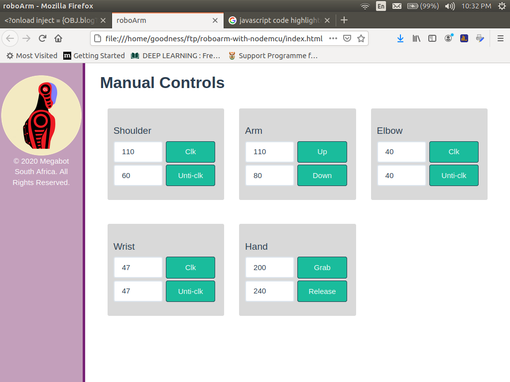
Figure-17
Figure-17 illustrates how we want our web interface to look like in the end. Because I wanted to include a logo image and a few third party files that can facilitate the speedy development of our web UIs and even help us quickly develop a responsive page, I decided to let the robot's web server run not on the NodeMCU but on a separate computer. You could of-course convert your images to base64 strings and write all your webpage code on a single file but I was not sure whether the final code for the web server, UIs, CSS and the client-side JavaScript could all fit into the NodeMCU's memory and if writing it this way would even turn out to be more practical than taking advantage of third party resources such as "font-awesome", "bootstrap" etc.
For this reason, the code that runs on the NodeMCU is just a WebSocket Client and the hardware driver code. All the web related stuff (back-end and front-end) are handled by an additional computer that needs to form part of the robot's NodeMCU's network. You are welcome to write to me if you wish to receive help on how you could write all you server scripts and front-end scripts in one page. Also the book that I recommended can help you write code that can make your NodeMCU work as a server instead of a client.
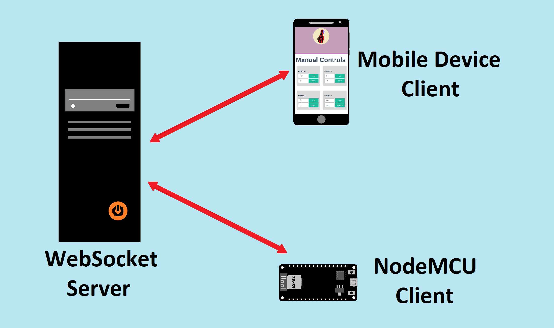
Figure-18
Basically, we want the server to act as a relay of command messages from any web browser client runing on a mobile device to all other clients connected to the server. Among the clients will be the NodeMCU which will be responsible for carrying out the relayed instructions and providing feedback whenever necessary. The feeback will then be relayed by the server to the rest of the clients connected to it.
The HTTP/HTTPS protocol is the most popular communication protocol among browsers but it was not built for the kind of communication that is required in our robot project. We need asynchronous biderectional communication between the server and each client but the HTTP protocol was designed such that the client always initiates a conversation and the server only responds to requests for information from clients. We, on the other hand, need the server to have the capacity to notify us whenever new information becomes available without ever needing to soliciting it.
Think for example about a situation in which a user has pressed a button on our robot's webpage-UI that commands the robot to perform a certain action. The webpage's code will generate an instruction message that will be propageted towards the server. Our desire is that the server should be able to send that instruction message over to the NodeMCU but if it were the case that we are dependent on the HTTP protocol, the problem that would immediately arise is that the NodeMCU would hardly ever know that the server possesses information that it needs to retrieve from the server by making a request for it.
As a means of solving this problem, some people have devised a scheme through which a client that anticipates that the server may come to be in possession of information that it may desire to retrieve keeps polling the server at a set interval until it gets hold of that piece of information. AJAX (Asynchronous JavaScript And XML) is an API built according to this principle and is aimed at addressing the HTTP protocol's limitations.
The reason why I am not very happy with AJAX and any other polling based technology is that they are very heavy on data. Fortunately for us, some smart coders out there have found a way to hack the HTTP protocol in order to make it behave in such a way that the server can send unsolicited messages to clients whenever it needs to do so. This is called the "WebSocket" protocol. A certain implementation of the WebSocket protocol called SocketIO also offers a fall-back plan to polling in case the WebSocket connection fails. For this reason and the fact that I personally feel that SocketIO prefers polling over WebSocket, I avoid using it and would much rather create my own mechanism for clients to sometimes test their WebSocket connections to see if they are still alive and to reconnect in the event of a failed connection.
The WebSocket protocol makes what is depicted in Amination-2 possible. As illustrated there, it is as though the message that emanated from the mobile device passed through the Websocket server straight to the NodeMCU. The truth of the matter though is that each client (the mobile client and the NodeMCU) each sends its message to the server and it is the server that passes that message to the other device. The clients cannot be able to communicate directly without the services of the server. Just because I passed too close to the subject, I will have you know that client to client communication does exist but is not the subject of our project. It is called WebRTC and I leave the responsibility to learn about it entirely on you if you wish to do so.
Animation-2
My programing language of choice is Node.js. It therefore comes as no surprise that I chose it for implementing the Websocket server. Please visit https://nodejs.org to learn how you can install Node.js on your machine. You can also try this link: https://nodejs.org/en/download/package-manager/ .
If you wish to install Node.js on a Debian system like Ubuntu using the "apt-get" package manager, you can use the following commands on your terminal:
Check if the installation was sucessful by using the following command:
If that fails, try entering this command:
Also, check if the Node.js Package Manager (NPM) is also installed by using this command:
If it is not installed, you may wish to install it by entering the command:
Now that Node.js is installed on your machine, let us finally consider the server code. Create a folder that you wish to store all your software for the NodeMCU project (perhaps name it "forNodeMCU"). I will assume that you have chosen to name your folder as I recommended from now on. Now, copy the code below and save it directly into the "forNodeMCU" folder and name it "server.js":
server.js
var server = require('http').createServer();
var WebSocketServer = require('ws').Server;
var wss = new WebSocketServer({ server: server });
var express = require('express');
var app = express();


app.use("/img", express.static(__dirname + '/img'));
app.use("/css", express.static(__dirname + '/css'));
app.use("/js", express.static(__dirname + '/js'));
app.use("/fonts", express.static(__dirname + '/fonts'));
app.use("/font-awesome", express.static(__dirname + '/font-awesome'));


app.get('/', function (req, res) { res.sendFile( __dirname + "/" + "index.html"); });
app.get('/esp', function (req, res) { res.send("Hello ESP"); });

wss.on('connection', function connection(ws) {

	console.log('Connection from client.');

	ws.on('message', function incoming(message) {

		wss.clients.forEach(function each(client) { client.send(message); });
		console.log('Got: ', message);
	});

	ws.send('You are now connected.');
});

server.on('request', app);
server.listen(80, function () { console.log('Listening on ' + server.address().port); });
Sketch-1
If you are already farmiliar with Node.js, you will immediately realise that the server code is very very basic. Its purpose can be summed up in these few words: 'relay any message from a client to all connected clients. This functionality is all we need for manual control of the robot but things get a little bit serious when automation enters the picture as we shall see later.
The purpose of Lines 1 through 5 is to link our "server.js" code with third party libraries that are essential to our application. Line 1 adds a library that deals with HTTP protocol procedures for our server, Line 2 adds the library that handles the WebSocket procedures and Line 4 adds a third party application framework library that offers useful features that are desirable in an HTTP server.
The purpose of Lines 8 to 12 is to let our server apllication know which directories the server can expect to acquire resources from. As the project develops, we will need a folder for storing image files, a folder for css files, for JavaScript files, for font files and font-awesome files and we choose to name them "img", "css", "js", "fonts" and "font-awesome" respectively.
The "__dirname" keyword in each line denotes the address of the parent directory that our "server.js" file belongs to (the adrress for the "forNodeMCU" folder/directory). Thus, the expression: __dirname + '/img' means the address of the "server.js" file concatenated with (joined with) the string "/img". As an example, suppose __dirname = "/home/myusername/forNodeMCU", then __dirname + "/img" = "/home/myusername/forNodeMCU/img" .
As a security feature, if a file is not located inside any of these directories declared by the lines of code from Line 8 to 12, our server application refuses to work with it.
Line 15 represents a piece of code that handles an HTTP request made to the server using the "GET" method. The name of the request is simply: "/". We could have chosen to make it something like "/home" or "/ourpage" etc. What that line of code means is that when the server receives a GET request by the name "/", it responds by sending a file called "index.html". The file "index.html" is our webpage-UI for controlling the robot arm and we will get to it later. The reason why this line of code is neccessary is that in order to control our robot arm, we need some sort of a User Interface (UI) for issuing commands to the robot and what I recommend in this project is a webpage that could be accessed from any smart phone or even computer.
Line 16 is a code that defines the server path that is entirely dedicated to the NodeMCU. I found it practical to have this line because we do not want a request from the NodeMCU to the server answered with a huge chunk of data (the index.html file). That is why the request made to the "/esp" path is set to return just the string "Hello ESP" to the NodeMCU.
Line 18 to 29 constitute the major part in our server code that handles WebSocket traffic. Using the WebSocket object that was created and instantiated (a new instance of it created from its constructor parent: "WebSocketServer" or equivalently "require('ws').Server") at Line 3, we can write code that handles the 'connection' WebSocket event. The event handler takes the form : wss.on('connection', callback-function).
Looking at the 'connection' WebSocket event handler, it is clear that it is an invokation of a function that takes two arguments. The second argument, the callback function, takes a WebSocket object as an argument that we choose to call "ws". This is an object that we get from a WebSocket client that attempts to connect to the "server.js" server.
Thus, in the event of a successful connection to our server, our server does three things in response: the code in Line 20, the code block from Line 22 to 26 and the code in Line 28. The code in Line 20 simply logs the string "Connection from client." on the terminal as an output of the server. The code block from Line 22 to 26 is the piece that does the relaying of messages to all connected clients and we will come back to this part of the code soon. The code in Line 28 is where the server sends back a message to the newly connected client informing it that a successful connection with the server has been established. The Server uses the client's own WebSocket object to send back the message.
The code from Line 22 to 26 is itself another event handler. It is the event handler of the newly connected client's WebSocket object (the "ws" object). Therefore, it is clear at this point that the first event handler that we considered (that of the "wss" object is a factory that mass-produces event handlers with every new connection made to it.
The event handler for the "ws" object also takes two arguments: one a string and the other a callback function. In the case of the code block from Line 22 to 26 in Sketch-1, the string argument is the "message" literal and the callback function is tasked with two responsibilities. Line 24 is an expression of the first responsibility and Line 25 the second. Respectively, these translate to (1) looping through the entire record of connected clients stored in the array "wss.clients" and using each client's WebSocket object to send the very message that the server has just recieved from one of its client's "message" fired events and (2) logging on the server's stdout (standard output) on the terminal the message that the server has just gotten.
That's just what the server does in a nutshell. I am glad that the complexity of the code that I wrote for the NodeMCU remained as simple as it did (thanks to the issues that I explained earlier in this article) because my choice to present it first in this article offers me the opportunity to provide detailed explanations of how it works without compromising too much simplicity in favor of clarity. I will not attempt to repeat this procedure (detailed line by line explanations of the code) as soon as we begin to consider the code for the Raspberry Pi computer because it is a little bit more involved than that for the NodeMCU's. I consider the simple code that I wrote for the NodeMCU a stepping stone towards an understanding of the code for the Raspberry Pi computer.
The third party libraries that our code uses will need to be installed into your machine using NPM. The "http" module is a built in module of Node.js. Enter the following commands on your terminal that is pointing into your "forNodemcu" folder in order to install the libraries:
For the ws library:
For the express library:
We want our webpage-UI to have the same appearance as illustrated in Figure-17. We will need to create the following folders within the "forNodeMCU" folder: "img", "css", "js" and "font-awesome". You need to create your own logo and save it in the "img" folder and to download the following files that need to be placed within their appropriate directories:
Make sure that your font-awesome files are arranged as follows:
You must have a "forNodeMCU/font-awesome/css/font-awesome.css" file and a "forNodeMCU/font-awesome/css/fonts" directory with 5 font-awesome files: "FontAwesome.otf", "FontAwesome.eot", "FontAwesome.svg", "FontAwesome.ttf" and "FontAwesome.woff" inside.
With all these files in place, let us now turn our attention to the HTML code for the webpage-UI. Copy the code below and save it as "index.html" within the "forNodeMCU" folder.
index.html
<!DOCTYPE html>

<html lang="en">

	<head>

		<title>roboArm</title>

		<meta charset="utf-8">
		<meta name="viewport" content="width=device-width, initial-scale=1">

		<link href="font-awesome/css/font-awesome.css" rel="stylesheet">
		<link href="css/bootstrap.css" rel="stylesheet">
		<link href="css/settings.css" rel="stylesheet">

		<script>
			// Insert your WebSocket JavaScript code here
		</script>
	</head>

	<body lang="en">

		<script src="js/bootstrap.js"></script>
	</body>
</html>
Sketch-2
You will probably notice that as it is at present, our HTML code does nothing substantial except to link our page with other pre-written resource codes such as the "bootstrap.css" file and the font-awesome files. Funny enough, I never got to the point of using the font-awesome files in the code that I wrote for the NodeMCU but since you might desire to continue building on the code in your project, I decided to make room for it. I for one had intended to take advantage of the font-awesome resources in my project.
Looking again at Figure-17, you will notice that the graphical side of our webpage consists of two sections: a side-bar on the left and the rest of the area on the right of the side-bar in which all the controls are contained. In line with this, let us add the following code within our "body" element:
<div class = "col-md-2 side-bar">

	<img src="img/logo.png" height = "162px;"/>

	<div class = "col-md-12">
		<p style = "text-align: center;">
			© 2020 Megabot South Africa. All Rights Reserved.
		</p>
	</div>
</div>


<div class = "col-md-10">

	<div class = "col-md-12">

		<h2>
			<b>Manual Controls</b>
		</h2>

		<!-- Insert code for the 5 controls here -->
	</div>
</div>
Sketch-3
Please consult the "settings.css" file that I have written and study it. It contains all the css settings pertaining to the appearence our webpage. Keywords such as "side-bar" are defined in there.
Also, please make appropriate changes to the code in Sketch-3 to meet your needs. For example, if you wish to have the copyright line preserved in your web-UI, please edit it accordingly to reflect your message.
Figure-17 informs us that there should be 5 controls for each of the five motors that must be inserted within the body of the "div" element defined from Line 15 to 22 immediately below the code for the "h2" element defined from Line 17 to 19 in Sketch-3. Because the entire code for all 5 controls is big, I am going to show only the code for the "Shoulder" control in Sketch-4 and I will leave the responsibility to figure out how to make copies of it and how to edit each copy such that you end up with the entire picture to you. Also, I will provide a download link for the entire HTML code in compressed format later. Nevertheless, my recommendation is that you should endeavor to work things out yourself the hard way.
<div class = "col-md-4">

	<div class = "sect">

		<h4>Shoulder</h4>

		<div class = "unit-line">
			<div class="hlf">
				<input class="form-control" type = "text" id = "m4dr0" name = "m4dr0" value = "110"/>
			</div>

			<div class="hlf">
				<button class = "btn btn-primary" onmousedown = "cmd('motor4:0')" ontouchstart = "cmd('motor4:0')"
					onmouseup = "cmd('motor4:s')" ontouchend = "cmd('motor4:s')">Clk</button>
			</div>
		</div>

		<div class = "unit-line">
			<div class="hlf">
				<input class = "form-control" type = "text" id = "m4dr1" name = "m4dr1" value = "60"/>
			</div>

			<div class="hlf">
				<button class = "btn btn-primary" onmousedown = "cmd('motor4:1')" ontouchstart = "cmd('motor4:1')"
					onmouseup = "cmd('motor4:s')" ontouchend = "cmd('motor4:s')">Unti-clk</button>
			</div>
		</div>

		<br style = "clear: both;">

	</div>

</div>
Sketch-4
Now, you might notice that the code in Sketch-4 consists of two pieces of code that I chose to call "unit-lines". The first is defined from Line 7 to Line 16 and the second from Line 18 to 27. We have defined a textbox and a button in each unit-line. The purpose of the textbox is to provide the user with the ability to set the magnitude of the PWM duty cycle that he/she desires to drive the Shoulder" motor at. The purpose of the button is to provide the means through which our command to the motor can be activated from. Each unit-line is associated with a direction that the motor can rotate in.
Here is an explanation of some of the conventions that I chose to adopt for the robot project associated with the code in Sketch-4:
I undertook an exercise to determine what the various default PWM duty cycle values for each motor and each direction should be. Of course, because there probably will be differences between your hardware and mine and because we have different tastes as regards speed, my values need not be the same as yours. Those values that I found are the ones that I plugged into the "value" attributes of each unit-line's textbox.
With this template that I have provided in Sketch-4 for the "Shoulder" control, write code that will represent the rest of the other 4 controls and add it to your "index.html" file. Let us now consider what the client-side JavaScript that we want to handle the WebSocket stuff should look like. Looking back at Sketch-2, you should insert your JavaScript code within the "head" element at the position marked by the comment in Line 17.
// Replace with the IP address of your server
var ws = new WebSocket("ws://000.000.000.000");

ws.onopen = function(e) { alert('Connection to server opened'); }
ws.onclose = function(e) { alert("Connection to server closed"); }

ws.onmessage = function(e) {

	var data = e.data;
	//write code to use this feeback data here
}

function cmd(nm) {

	if (nm.indexOf('motor') != -1) {

		var msgParts = nm.split(':');
		var motor = Number(msgParts[0].substring(5));
		var duty = (msgParts[1] == 's' ? 0 : document.getElementById('m' + motor + 'dr' + msgParts[1]).value);

		ws.send(nm + ':' + duty);
	}

	else ws.send(nm);
}
Sketch-5
Looking at Sketch-5, Line 2 is where we instantiate our web browser WebSocket object. This process also works to connect our client-side JavaScript to the server at the IP address that we will specify.
Lines 4 and 5 are two event handlers, one for the "open" event and the other for the "close" event and they both simply just alert a user to the effect that the event has taken place. The third event handler is the code block from Line 7 to 11 and this one responds to the "message" event. The contents of that event handler will be authored by you should you be interested in using the NodeMCU for your project because my opportunity to write that code was blown away (at least for now) the day my reckless behavior blew my NodeMCU unit apart. Do not worry though, you will have the code for the Raspberry Pi as an example to learn from.
The function defined from Line 13 to 25 is the one that the buttons in our web-UI use to send messages to the server using the WebSocket protocol. It takes one argument called "nm" (which is a shorthand for "name" - command name). It is a string variable. The function takes this argument and combines it with the text of the corresponding textbox to generate a string literal of the form "motorX:Y:Z" that is sent to the NodeMCU via the "ws" object.
Our discussion of the webpage-UI ends here. Download the entire template of the front-end and back-end code for the robot here and compare it with what you have compiled thus far: forNodeMCU.zip
Although there are many ways to program the NodeMCU, I recommend using the Arduino IDE to compile AT codes and to upload them into the NodeMCU using the serial protocol (UART) for you. The book that I recommended before can be very helpful in this regard. Assuming that everything went well for you and you have got your NodeMCU board properly installed in your Aduino IDE, copy the code below into your Arduino IDE, save as a new Sketch "wsClient.ino" within the "forNodeMCU" folder, and upload it into your NodeMCU board.
wsClient.ino
#include <WiFi.h>
#include <WebSocketClient.h>

const char* ssid     = "your-WIFI-network-name";
const char* password = "your-WIFI-network-password";

char path[] = "/esp";
char host[] = "your-server-IP-address";

WebSocketClient webSocketClient;
WiFiClient client;

int currentDir = 0;

const int motor0d0 = 23; const int motor0d1 = 22; const int motor1d0 = 3;
const int motor1d1 = 21; const int motor2d0 = 2; const int motor2d1 = 18;
const int motor3d0 = 5; const int motor3d1 = 17; const int motor4d0 = 16;
const int motor4d1 = 4;

// setting PWM properties
const int freq = 500;
const int resolution = 8;

const int channel0 = 0; const int channel1 = 1; const int channel2 = 2;
const int channel3 = 3; const int channel4 = 4; const int channel5 = 5;
const int channel6 = 6; const int channel7 = 7; const int channel8 = 8;
const int channel9 = 9;

int channels[5][2] =    {{channel0, channel1}, {channel2, channel3},
						{channel4, channel5}, {channel6, channel7},
						{channel8, channel9}};

int motors[5][2] =      {{motor0d0, motor0d1}, {motor1d0, motor1d1},
						{motor2d0, motor2d1}, {motor3d0, motor3d1},
						{motor4d0, motor4d1}};


void switchOff() {

  digitalWrite(motor0d0, LOW); digitalWrite(motor0d1, LOW);
  digitalWrite(motor1d0, LOW); digitalWrite(motor1d1, LOW);
  digitalWrite(motor2d0, LOW); digitalWrite(motor2d1, LOW);
  digitalWrite(motor3d0, LOW); digitalWrite(motor3d1, LOW);
  digitalWrite(motor4d0, LOW); digitalWrite(motor4d1, LOW);
}


void setup() {

  switchOff();

  // configure motor PWM functionalitites
  ledcSetup(channel0, freq, resolution); ledcSetup(channel1, freq, resolution);
  ledcSetup(channel2, freq, resolution); ledcSetup(channel3, freq, resolution);
  ledcSetup(channel4, freq, resolution); ledcSetup(channel5, freq, resolution);
  ledcSetup(channel6, freq, resolution); ledcSetup(channel7, freq, resolution);
  ledcSetup(channel8, freq, resolution); ledcSetup(channel9, freq, resolution);

  // attach the channel to the GPIO to be controlled
  ledcAttachPin(motor0d0, channel0); ledcAttachPin(motor0d1, channel1);
  ledcAttachPin(motor1d0, channel2); ledcAttachPin(motor1d1, channel3);
  ledcAttachPin(motor2d0, channel4); ledcAttachPin(motor2d1, channel5);
  ledcAttachPin(motor3d0, channel6); ledcAttachPin(motor3d1, channel7);
  ledcAttachPin(motor4d0, channel8); ledcAttachPin(motor4d1, channel9);

  //Wifi Config
  Serial.begin(115200);
  delay(10);

  // We start by connecting to a WiFi network
  Serial.println();
  Serial.println();
  Serial.print("Connecting to ");
  Serial.println(ssid);

  WiFi.begin(ssid, password);

  while (WiFi.status() != WL_CONNECTED) {

	delay(500);
	Serial.print(".");
  }

  Serial.println("");
  Serial.println("WiFi connected");
  Serial.println("IP address: ");
  Serial.println(WiFi.localIP());

  delay(5000);

  // Connect to the websocket server
  if (client.connect(host, 80)) { Serial.println("Connected"); }
  else { Serial.println("Connection failed."); while(1) { /* Hang on failure*/ } }

  // Handshake with the server
  webSocketClient.path = path;
  webSocketClient.host = host;

  if (webSocketClient.handshake(client)) { Serial.println("Handshake successful"); }
  else { Serial.println("Handshake failed."); while(1) { /* Hang on failure*/ } }

  switchOff();
}


void loop() {

  String data;

  if (client.connected()) {

	webSocketClient.getData(data);

	if (data.length() > 0) {

	  Serial.print("Received data: ");
	  Serial.println(data);

	  if (data.indexOf("motor") != -1) {

		char motor = data.substring(5,6).toInt();
		String dir = data.substring(7,8);

		if (dir == "s") {

		  ledcWrite(channels[motor][currentDir], 0);
		  digitalWrite(motors[motor][currentDir], LOW);
		}

		else {

		  currentDir = dir.toInt();
		  char duty = data.substring(9).toInt();
		  ledcWrite(channels[motor][dir.toInt()], duty);
		}
	  }
	}
  }

  else {

	Serial.println("Client disconnected.");
	delay(3000);  // wait to fully let the client disconnect
	while (1) {/* Hang on disconnect.*/ }
  }
}
Sketch-6
Although simple, the code for the NodeMCU board is sort of big. This is a reminder that although very advanced for an MCU (Micro Controller Unit), the ESP chip is still primitive compared to today's computers. We still need to ensure that the code we write does not take up too much of the chip's memory. Nevertheless, it must be said that the ESP chip is truly a giant leap from the Microchip PIC16F, PIC18F and PIC32 type of MCUs. I personaly like the ESP revolution because the ESP32 WROOM, for example, possesses sufficient memory (about 4Mb) to allow us more freedom to work with strings and objects: that is to say that doing string manipulation stuff and other high level coding tricks is easier with the ESP than it was with the MCUs we were previously acquainted.
As for Sketch-6, Lines 4 to 35 are all declaration codes for all the variables and constants that are going to be used later in the code. Looking at Lines 4 and 5, it is clear that we need to provide a WiFi network that our NodeMCU, the server and the mobile device clients from which the robot will be controlled all need to be part of.
The purpose of the "currentDir" variable in Line 13 is that when we desire to terminate a PWM output to a specific motor, it will soon be clear that it is easy for us to know which motor we want to target with the stop command but not easy to know which direction because from the instruction "motorX:s", it is not easy to guess what took the place now occupied by the "s" in the direction part of the instruction. It is for this reason that it is important for us to store the currently chosen direction in a variable.
Lines 15 to 18 are declarations that tell the NodeMCU which pins to associate with each of the specified more human intuitive contants such as "motor3d0" (shorthand for motor3-direction0). This is where we specify the address of each of the constants.
Concerning Lines 20 to 22, the resolution constant refers to the bit-width of the duty cycle's distinct values that could be selected. The 8 bit resolution that I chose implies that we can select a duty cycle between 0 and ((2^8 - 1) = 255). The ESP chip that the NodeMCU uses possesses up to 16 channels of LED Control type PWM channels (LEDC) that are 16bit wide. The greater the frequency you choose, the smaller the resolution will be. According to my research, because our chosen frequency is less than 1KHz, we could choose a resolution of up to 16 bit but 8bit is good enough.
The formular that I got (see this discussion: https://esp32.com/viewtopic.php?t=6701) is that:
| max-resolution | = |
|
||||
| log 2 | ||||||
| max-resolution | = |
|
||||
| log 2 |
| = 17 > 16 |
Lines 24 to 27 are declarations that tell the NodeMCU which pins to associate with each of the specified PWM channel constants. We need 10 channels because each of the 5 motors needs two channels to correspond with its two directions of rotation.
As for Lines 29 to 35, it will soon be clear that it is easier to programatically reference a motor or channel per desired direction when we have stored the channel and motor addresses (yes, I mean physical hardware addresses) in a 5 x 2 matrix.
The code block from Line 38 to 45, is a function that we use to silence all outputs on the NodeMCU pins that serve as outputs.
Peering into the built in "setup( )" function, the first half (Lines 52 to 64) of the code pertains to PWM configurations while the other half (Lines 66 to 100) pertains to WiFi and Websocket connection configurations.
Just as I briefly mentioned above, the NodeMCU possesses up to 16 channels of LED Control channels. We need to take advantage of just 10 of these in our project. In Lines 53 to 57, we setup each of these 10 channels and in Lines 60 to 64, we attach these channels to their appropriate pins of the NodeMCU.
In Line 67, the code instructs the NodeMCU to open a serial comunication with an external device. In our project, that device is the computer from which we program the NodeMCU using the Arduino IDE. It is not neccessary to communicate any feedback messages to the computer from the NodeMCU as done in this example but it is very useful to do so for debuging purposes. Since it may be your desire to continue developing the code of the NodeMCU so that it may also be capable of automation, I recommend that you do not remove this feature in your code until after you have successfully written and debuged your final code. Conversely, you could elect to convey post WebSocket connection feedback messages via the WebSocket connection.
Between Line 76 and 87, the NodeMCU attempts to establish a WiFi connection into our network (Line 76), keeps checking the status of such a connection until a connection is established (Lines 78 to 82) and sending confirmatory feedback messages to the serial monitor software running on our computer that we use for programing the NodeMCU that the connection was successful (Line 84 to 87). The long delay called for in Line 89 is neccessary in order to ensure a smooth transition from the serial protocol to the WebSocket protocol for the NodeMCU chip.
From Line 91 to 100, the code instructs the NodeMCU to try to establish an HTTP connection to the server and to report the results through the serial connection (Lines 92 and 93) and to upgrade to the WebSocket protocol (Lines 96 and 97) and to report the results through the serial connection (Lines 99 and 100).
The purpose of Lines 50 and 102 is to silence all outputs of the NodeMCU that are connected to our motors.
The entire control algorithm for the robot resides within the infinite "loop( )" function from Line 106 to 146. Granted that a WebSocket connection is in place (this condition is checked in Line 110), at every instance that the infinite "loop( )" is invoked, Line 112 scans the WebSocket object (the "webSocketClient") for new messages and uses the "webSocketClient.getData( )" function to store the string info it finds into the "data" variable we declared in Line 108 and passed to the function as an argument.
The code block from Line 114 to 136 is the one that processes the info received from the WebSocket if it is available. Over and above the fact that the code notifies the serial monitor software of the data it receives via the WebSocket connection (Lines 116 and 117), it also extracts two pieces of information from the data (provided that the information bears the "motor" substring signature in it): 'the target motor number' and 'the specified direction' and stores these things within the "motor" and "dir" variables respectively (Lines 121 and 122).
You may have noticed that the "motor" variable is declared as an integer while the "dir" variable is declared as a string. The reason for declaring the "dir" variable as a string is that the three possible values that are admissable to this variable are "0", "1" and "s" and, thus, at least one of them cannot easily be modeled as an integer.
The code block defined from Line 124 to 128 is carried out when the command sent to the NodeMCU via WebSocket is a stop command and the code block from Line 130 to 135 is carried out when the command is not a stop command.
The code block defined from Line 124 to 128 simply switches OFF the PWM generation and sets the same pin that issued that PWM pulse train to a digital Low so as to ensure that the motor stops moving. You may have noticed that this code takes as an input meant for direction the value of the "currentDir" variable. In the event of a successful generation of PWM to a motor via a certain pin, the variable would have been set to an appropriate value as can be descerned by considering the code block defined from Line 130 to 135.
Another thing worth noting is that selecting a desired motor or channel using a motor number or direction number has been reduced to a simple exercise of just referencing the contents of the channels and motors two dimensional arrays.
We have come to the end of our discussion of the NodeMCU software. At this point, navigate to the "forNodeMCU" folder in your terminal and enter the command:
Depending on the name that your installed Node.js might have, it might be neccessary for you to run the code specified below instead:
Suppose the terminal throws an error to the effect that a certain Node.js module has not been installed, read the error message carefully to determine which module it is and install it using NPM.
Assuming that everthing went well for you, the terminal will output a message similar to:
In that case, you now need to take hold of your smart phone and connect to the WiFi network that your server computer and the NodeMCU are connected to and enter the IP address of the server on your browser and access the page the server will give you and start controlling your robot! Otherwise, you will need to carefully debug all your code scripts. Let us hope that it will not come to that though.
The Raspberry Pi computer is a very powerful DIY control unit. It is a fully fledged computer that can also be used like an MCU because of its GPIO header. Because of this, I decided to let it be the brain of the entire robot soon after my prospects with the NodeMCU disappeared. The server and the entire algorithmic codes for controlling the robot are all hosted within the Raspberry Pi computer.
Compared to the code we have dealt with thus far, the code for the Raspberry Pi computer is very big and is not complete. The software that I have written thus far allows the robot to be controlled manually, allows the robot to calibrate its position measuring encoders and to automatically move the robot arm to a home position thereafter (a process I call "Zeroing") and provides a graphical, interactive and user-friendly (hopefully you too may find it so) wizard that allows a user to create, delete, and run an automation sequence. I am yet to expand the software to allow for sequence editing. At present, the only way to edit an automation sequence is to hack the JSON style "sequence.seq" file that stores all automation sequences for the robot.
The code for the server and all the control algorithms is one unit on runtime and all of it resides in the Raspberry Pi computer's file system. Because it would otherwise be very big and difficult to debug, I chose to break it down into several chunks that I call "modules" (similar to the NPM's "node_modules" filing structure).
The design philosophy that I adopted with regard to the Raspberry Pi computer is that the robot needs to have a hardware protection trip system because of the many losses that I suffered before this descision. Because of this, two independently triggered pieces of software run on the Rasberry Pi for every normal operation of the robot. One is the "supervisor.js" script and the other is the "wsServer.js" software. The purpose of the "supervisor.js" script is to trip the robot if the "wsServer.js" software fails for any reason. The "wsServer.js" script is the code that powers all the robot's operations.
The files need to be arranged as depicted in Figure-19 within a folder that you may call "forRaspberryPi" somewhere within your Raspberry Pi's file system. As you can see, directly within the "forRaspberryPi" folder are the "supervisor.js" and "wsServer.js" files. There are also four directories within our project's home directory: the "modules", "node_modules", "pg" and the "storage" folder.
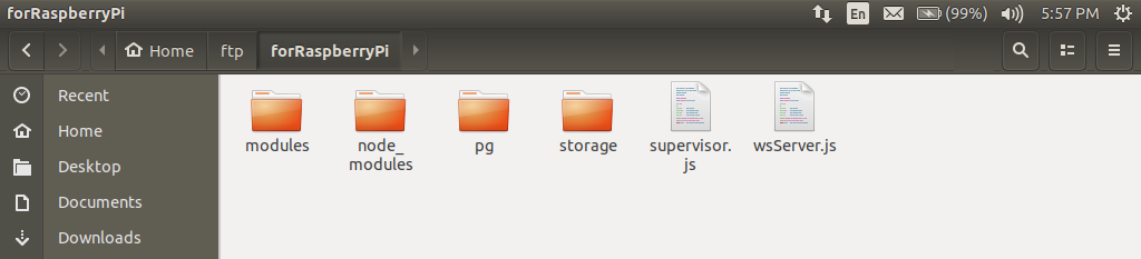
Figure-19
The "modules" folder contains extension scripts for the "wsServer.js" software called "hardware.js", "runSeq.js", "sequence.js" and "zeroEncoders.js". I will explain these later. The name "pg" for one of the folders within the "forRaspberryPi" home folder is a shorthand for the word "pages". The folder that bears this name contains all the front-end files for the robot. The "storage" folder houses the "sequence.seq" file that is used by the robot's software to store all automation sequences that users create for the robot and the "node_modules" folder is generated and managed by NPM as you install third party modules for the project. I prefer local node_modules installations as opposed to global installations because it is easier to make our project portable when all the dependency modules are contained within the home folder of our project.
supervisor.js
var net = require('net');
const Gpio = require('onoff').Gpio;

var HOST = 'localhost';
var PORT = 8008;
var communicationTracker = 0;
var tripStatus = true;

const trip = new Gpio(12, 'out');

// Create Server instance
var server = net.createServer(onClientConnected);
server.listen(PORT, HOST, function() {

	console.log('server listening on %j', server.address());
});

function onClientConnected(sock) {

	var remoteAddress = sock.remoteAddress + ':' + sock.remotePort;
	console.log('new client connected: %s', remoteAddress);

	if (tripStatus) { sock.write("msg>system-is-tripped"); }

	sock.on('data', function(data) {

		communicationTracker = 0;

		if (data == "please-enable-system") {

			systemTripLoop();
			unTripTheSystem();
			sock.write("msg>system-is-enabled");
		}

		if (data == "please-inform-trip-status") {

			sock.write(tripStatus ? "msg>system-is-tripped" : "msg>system-is-enabled");
		}
	});

	sock.on('close',  function () {

		console.log('connection from %s closed', remoteAddress);
	});

	sock.on('error', function (err) {

		console.log('Connection %s error: %s', remoteAddress, err.message);
	});
};


function systemTripLoop() {

	setTimeout(() => {

		communicationTracker++;

		if (communicationTracker > 4) { tripTheSystem(); }
		else { systemTripLoop(); }
	}, 70);
}


function tripTheSystem() {

	console.log(' Triping the system...');
	trip.writeSync(0);
	tripStatus = true;
}


function unTripTheSystem() {

	communicationTracker = 0;
	console.log(' Untriping the system...');
	trip.writeSync(1);
	tripStatus = false;
}
Sketch-7
From a high level point of view, the whole idea of the "supervisor.js" software is this: whenever the "wsServer.js" fails because of a software bug or some other reason, it sometimes sets some of the motors of the robot runing at muximum power such that whem the arm encounters an obstacle to its rouge motion (usually its very own body), the effect is that some of the gearboxes breakup. To prevent this occurance, we need to find a way of knowing that the "wsServer.js" has crushed. One way that I deviced for this project is to let the "wsServer.js" script constantly communicate with an external program (the "supervisor.js" script) that should regard failure of communication to indicate that the "wsServer.js" has crushed and thus trip the robot system.
Because communication between the "supervisor.js" software and the "wsServer.js" software does not involve a browser, we need not use WebSockets. That is why I chose the "net" module for this communication (hence Line 1 of our Sketch-7 code). The "supervisor.js" program is the server while the "wsServer.js" is the client.
Also, because the "supervisor.js" needs to be able to switch hardware ON/OFF, I chose to use the "onoff" module in the "supervisor.js" program because of its simplicity. The "wsServer.js" program is a much more agressive user of the GPIO hardware and even needs high speed sampling of the input pins connected to our encoders in order to function properly. For this reason, I chose to use the "pigpio" library for the server. This is actually a wrapper around the C language "pigpio" library and has unfettered access to the GPIO pins at kenerl mode level.
Basically, how the code works is that at a regular interval (I set my code to once every 70ms), the code keeps encreamenting the "communicationTracker" variable by a unit. Any successful communication with the "wsServer.js" program keeps resetting this count and preventing it from accumulating to an undesirable total that trips the system (in my case a value of 4). These are all random values of cource and you are free to choose whatever values that you feel will work for you.
wsServer.js
var server = require('http').createServer();
var WebSocketServer = require('ws').Server;
var wss = new WebSocketServer({ server: server });
var express = require('express');
var app = express();
var net = require('net');


var hardware = require('./modules/hardware');
var zeroEncoders = require('./modules/zeroEncoders');
var sequences = require('./modules/sequences');
var runSeq = require('./modules/runSeq');


app.use("/img", express.static(__dirname + '/pg/img'));
app.use("/css", express.static(__dirname + '/pg/css'));
app.use("/js", express.static(__dirname + '/pg/js'));
app.use("/fonts", express.static(__dirname + '/pg/fonts'));
app.use("/font-awesome", express.static(__dirname + '/pg/font-awesome'));


app.get('/', function (req, res) {
	res.sendFile( __dirname + "/pg/" + "index.html");
});


var HOST = 'localhost';
var PORT = 8008;
var client = new net.Socket();


client.connect(PORT, HOST, function() {
	console.log('Client connected to: ' + HOST + ':' + PORT);
});

client.on('data', function(data) {

	var info = data.toString();
	console.log('Client received: ' + data);

	if (info.endsWith('exit')) { client.destroy(); }

	if (info.indexOf("msg>system") != -1) {
		wss.clients.forEach(function each(client) { client.send(info); });
	}
});

// Add a 'close' event handler for the client socket
client.on('close', function() { console.log('Client closed'); });
client.on('error', function(err) { console.error(err); });


function keepSupervisorHappy() {

	setTimeout(() => {

		client.write('Still alive');
		keepSupervisorHappy();
	}, 160);
}

function getTripStatus() {
	client.write('please-inform-trip-status');
}

var clientCount = 0;

wss.on('connection', function connection(ws) {

	console.log('Connection from client' + (++clientCount));

	hardware.trig.join("sw1", "wss", (obj) => {
		wss.clients.forEach(function each(client) {
			client.send(JSON.stringify(obj));
		});
	});

	hardware.trig.join("sw2", "wss", (obj) => {
		wss.clients.forEach(function each(client) {
			client.send(JSON.stringify(obj));
		});
	});

	hardware.trig.join("sw3", "wss", (obj) => {
		wss.clients.forEach(function each(client) {
			client.send(JSON.stringify(obj));
		});
	});

	hardware.trig.join("sw4", "wss", (obj) => {
		wss.clients.forEach(function each(client) {
			client.send(JSON.stringify(obj));
		});
	});

	hardware.trig.join("sw5", "wss", (obj) => {
		wss.clients.forEach(function each(client) {
			client.send(JSON.stringify(obj));
		});
	});


	hardware.trig.join("encoder1", "wss", (count) => {
		wss.clients.forEach(function each(client) {
			client.send("display=1 motor1-counter:" + count);
		});
	});

	hardware.trig.join("encoder2", "wss", (count) => {
		wss.clients.forEach(function each(client) {
			client.send("display=2 motor2-counter:" + count);
		});
	});

	hardware.trig.join("encoder3", "wss", (count) => {
		wss.clients.forEach(function each(client) {
			client.send("display=3 motor3-counter:" + count);
		});
	});

	hardware.trig.join("encoder4", "wss", (count) => {
		wss.clients.forEach(function each(client) {
			client.send("display=4 motor4-counter:" + count);
		});
	});

	hardware.init();

	keepSupervisorHappy();
	setTimeout(() => { getTripStatus(); }, 500);

	ws.on('message', function incoming(message) {

		wss.clients.forEach(function each(client) {
			client.send(message);
		});

		if (message.indexOf('createSeq(') != -1) {

			var str = message.substring(10, message.indexOf(")"));

			sequences.createSeq(str, (err, res) => {

				if (err) { ws.send('Show_message: ' + err); }

				else {

					if (res == "file-saved") {
						ws.send("Feedback>" + res);
					}
				}
			});
		}

		else if (message.indexOf('abortCreation(') != -1) {

			var str = message.substring(14, message.indexOf(")"));

			sequences.abortCreation(str, (err, res) => {

				if (err) { ws.send('Show_message: ' + err); }
				else { ws.send("Feedback>" + res); }
			});
		}

		else if (message.indexOf('editSeq(') != -1) {

			var arg = message.substring(8, message.indexOf(")"));
			var nm = arg.split("|")[0];
			var strCoordinate = arg.split("|")[1].split(",");
			var coordinate = [];
			var index = Number(arg.split("|")[2]);

			strCoordinate.forEach(function each(coo) {
				coordinate.push(Number(coo));
			});

			sequences.editSeq(nm, coordinate, index, ws, (err, res) => {

				if (err) { ws.send('Show_message: ' + err); }
				else { ws.send("Feedback>" + res); }
			});
		}

		else if (message.indexOf('readSequences()') != -1) {

			sequences.getAllSeqNames((err, res) => {

				if (err) { ws.send('Show_message: ' + err); }
				else { ws.send("Feedback>" + JSON.stringify(res)); }
			});
		}

		else if (message.indexOf('runSeq(') != -1) {

			var str = message.substring(7, message.indexOf(")"));

			runSeq.run(str, (err, res) => {

				if (err) { ws.send('Show_message: ' + err); }
				else { ws.send("Feedback>" + JSON.stringify(res)); }
			});
		}

		else if (message.indexOf('request-system-enable') != -1) {
			client.write('please-enable-system');
		}

		else if (message.indexOf('zero-all-encoders') != -1) {

			zeroEncoders.effectZero((msg) => {

				wss.clients.forEach(function each(client) {
					client.send(msg);
				});

				wss.clients.forEach(function each(client) {
					client.send('hide-splash');
				});
			});
		}

		else if (message.indexOf('zero-encoders') != -1) {
			zeroEncoders.effectZero((msg) => {
				ws.send(msg); ws.send('hidden-zeroing-complete');
			});
		}

		else if (message.indexOf('motor-cmd=>') != -1) {
			hardware.drive(message.replace('motor-cmd=>', ''));
		}
	});

	ws.send('You are now connected.');
});

server.on('request', app);

server.listen(80, function () {
	console.log('Listening on ' + server.address().port);
});
Sketch-8
As you can see, the "wsServer.js" code is big compared to that of the NodeMCU but it could have been much bigger had I not chosen to break it down into a number of modules. Lines 9 to 12 of Sketch-8 connect our "wsServer.js" with external extention modules that are located in the "modules" folder.
The "hardware.js" module deals with GPIO matters. It is the hardware driver library of the project. You will notice that begining from Line 73 to Line 128 in Sketch-8, several calls are made to this module for various services such as invoking the "hardware.init( )" function (whose purpose is to issue the command for a scan of all limit switches to be made so as to update the system of their values) and attaching callback functions created on the WebSocket side of the system to the events generated when limit switches and encoder switches are triggered.
Now, why is it neccessary to attach a callback function from the "wsServer.js" script's side to a switch managed from the "hardware.js" side? Well, when a switch is triggered either ON or OFF, the "hardware.js" library needs to know this information for its internal operations, the "wsServer.js" script needs to know the same information in order to relay it to the webpage-UI that is accessed by the user and as we shall soon see, other libraries (such as the "zeroEncoders.js") also need the same information for their own internal processes sometimes.
How then can the "hardware.js" library share its info with all interested parties? Initially, I chose to exploit the services of the "event" module but soon ran into problems. The result was that the code was very bugy and I would often receive messages that read something like: "MaxListenersExceededWarning: Possible EventEmitter memory leak detected...". Finally, I decided to create a function within the "hardware.js" library whose sole responsibility is to add a callback function to a targeted switch and one whose purpose is to delete such a callback at will. This is what I had hoped to get from the "event" modules before I came to realize that it was a bit of an overkill for my application.
This arrangement makes it possible for me to pass on the scope within the location from which I choose to attach a callback function (such as the "wss" object available within the "wsServer.js" script) into a code that would otherwise battle to access such a scope from its location (such as the "hardware.js" module; it is devoid of the WebSocket object's scope).
I hope this stuff does not sound strange to you. If it does however, you might perhaps consider learning a bit more about JavaScript. Consider topics such as "Functions - scope and closures", "Object Oriented Techniques for JavaScript", the asynchronous nature of Node.js and "callback functions".
With regard to Lines 139 to 193, several calls are made to the "sequence.js" library. These are requests for the "sequence.js" library to provide services such as creating, deleting updating and reading a specified sequence.
Looking at Line 33 of Sketch-15 under the code for the UI's JavaScript much further towards the end of this article (if you wish), you might notice that the string that the first argument of the function "sequences.createSeq( )" accepts as a valid input is of the form "createSeq(" + seqName + ")" (see the code from Line 139 to 153 in Sketch-8). The same thing applies to the "sequences.abortCreation( )" function: the first argument accepts a string of form "abortCreation(" + seqName + ")".
The "sequences.editSeq( )" function takes 5 arguments: a string that identifies the name of a target sequence, the coordinate that needs to be updated into the targeted sequence that is being created (of the form "(00,00,00,00,00,00)"), the integer index value of where this coordinate should be pluged into the array of the sequence being created, the WebSocket object associated with the user's web browser client that initiated the process of creating an automation sequence and the callback function that must be evoked as soon as the "sequences.editSeq( )" function desires to communicate feeback data.
My decision as to how the robot should be automated is that since the robot has 5 degrees of motion, each of those degrees should be represented as a mere dimension in a 5 dimensional coordinate space system. That is to say that any unique movement of the robot to any location should be able to be represented by a unique coordinate variable withing our 5 dimensional coordinate space. As an example, my robot hardware has the robot arm's home position defined by the vector (82, -42, -30, 21, 10). This means that the sholder-part of the robot is 82 clockwise directional unit rotations away from the zero-point limit switch, the arm-part is 42 downward unit rotations from the zero-point limit switch, the elbow-part is 30 upward unit rotations (yes up is negative for the elbow and down is pisitive according to how I wired my encoder) from the zero-point limit switch, the wrist-part is 21 clockwise directional unit rotations from the zero-point limit switch and the hand is fully open.
As for the hand-part, its coordinate accepts only two possible (binary) values: 10 and 20. I chose this pair because owing to the terrible accuracy of the encoders used in our project, I have decided to declare an error of ±2 unit rotations (as measured by the encoders) to be acceptable. Thus, given the shoulder-part for example, any value from 84 to 80 is acceptable as the shoulder-part coordinate value that represents the home position for that part.
The algorithm that I have written for running an automation sequence is blind to a difference in value of less than 3 on the part of any coordinate. Since I could not use 1 and 0 as the binary inputs for the hand-part coordinate if I desired to maintain uniformity across all the 5 dimensions of motion as regards tolarence, I chose the numbers 10 and 20 to represent the situations "fully open" (as detected by a limit switch) and "closed" (as presumed after a set period - about 1.8s - of attempting to do so).
Given all these principles that I decided to adopt, programing the robot to perform any kind of action amounts to simply specifying a sequence of coordinates (or vectors) that it needs to sequentially assume (by moving each of the 5 parts associated with each dimension accordingly) until the set action is carried out. This implies that any automated action that the robot arm can do (like picking up an object from a certain spot and dropping it at another) is nothing but a sequence of well ordered coordinates.
Given a well formed automated sequence, a request to run it can be made to the "runSeq.run( )" function (located in the runSeq.js library). That is the purpose of the code block defined from Line 195 to 204. The "runSeq.run( )" function also takes two arguments such that the first argument is a string of the form: "runSeq(" + seqName + ")".
The code from Line 206 to 208 relays a message received from a webpage-UI via WebSocket to the "supervisor.js" code via an ordinary TCP network protocol socket connection so that it may untrip the robot arm as requested by a user.
The code from Line 210 to 222 and the code from Line 224 to 228 do almost similar things except that the later code runs covertly behind the scenes while the first runs with full visual effects. Both codes invoke the only publictly exposed function of the "zeroEncoders.js" library that triggeres a builtin algorithm that calibrates all dimensions of motion on the robot (except for the hand-part motor) and to move each robot part of those dimensions to their home positions after a zero reference calibration.
Similar to the manual control functionality that we discussed for the NodeMCU, the code from Line 230 to 233 is the gateway on the "wsServer.js" for a user to send commands to the "hardware.drive( )" function of the "hardware.js" library that does the processing and execution of all manual control commands. For the Raspberry Pi computer and for reasons that I honestly do not remember at present, I chose the instructions to take the form "mX dY Z" on the HTML side and "motor-cmd=>mX dY Z" from the client-side JavaScript where the X, Y and Z represent the motor number (from 1 to 5), the direction number (1, 2 or "stop") and the duty cycle (from 0 to 255). You may recall that I had chosen the form "motorX:Y:Z" for the NodeMCU. Please note that the deliminator that I chose for the Raspberry Pi is a space charecter (" ") and not the colon charecter (":").
hardware.js
var pigpio = require('pigpio');
var Gpio = pigpio.Gpio;

var disableObj = {

	m1: false, m2: false, m3: false, m4: false, m5: false,
	dir_choice: { m1: "d2", m2: "d1", m3: "d2", m4: "d1", m5: "d1" }
};

var clk = [false, false, false, false],
	dt = [false, false, false, false],
	aState = [false, false, false, false],
	aLastState = [false, false, false, false],
	counter = [0, 0, 0, 0];


/*#################### Output Settings ###################*/
const pwmDir1 = new Gpio(17, {mode: Gpio.OUTPUT});
const pwmDir2 = new Gpio(18, {mode: Gpio.OUTPUT});

const motor1 = new Gpio(27, {mode: Gpio.OUTPUT});
const motor2 = new Gpio(22, {mode: Gpio.OUTPUT});
const motor3 = new Gpio(23, {mode: Gpio.OUTPUT});
const motor4 = new Gpio(24, {mode: Gpio.OUTPUT});
const motor5 = new Gpio(25, {mode: Gpio.OUTPUT});

const motor_ls = {

	m1: motor1,
	m2: motor2,
	m3: motor3,
	m4: motor4,
	m5: motor5
};

const pwmModule = { d1: pwmDir1, d2: pwmDir2 };
/*#################### Output Settings ###################*/


/*####################### Input Settings ########################*/
const lim_sw1 = new Gpio(7, {
	mode: Gpio.INPUT, pullUpDown: Gpio.PUD_DOWN, alert: true
});

const pin_dt1 = new Gpio(9, {
	mode: Gpio.INPUT, pullUpDown: Gpio.PUD_DOWN, alert: true
});

const pin_clk1 = new Gpio(0, {
	mode: Gpio.INPUT, pullUpDown: Gpio.PUD_DOWN, alert: true
});


const lim_sw2 = new Gpio(16, {
	mode: Gpio.INPUT, pullUpDown: Gpio.PUD_DOWN, alert: true
});

const pin_dt2 = new Gpio(14, {
	mode: Gpio.INPUT, pullUpDown: Gpio.PUD_DOWN, alert: true
});

const pin_clk2 = new Gpio(15, {
	mode: Gpio.INPUT, pullUpDown: Gpio.PUD_DOWN, alert: true
});


const lim_sw3 = new Gpio(1, {
	mode: Gpio.INPUT, pullUpDown: Gpio.PUD_DOWN, alert: true
});

const pin_dt3 = new Gpio(5, {
	mode: Gpio.INPUT, pullUpDown: Gpio.PUD_DOWN, alert: true
});

const pin_clk3 = new Gpio(6, {
	mode: Gpio.INPUT, pullUpDown: Gpio.PUD_DOWN, alert: true
});


const lim_sw4 = new Gpio(13, {
	mode: Gpio.INPUT, pullUpDown: Gpio.PUD_DOWN, alert: true
});

const pin_dt4 = new Gpio(19, {
	mode: Gpio.INPUT, pullUpDown: Gpio.PUD_DOWN, alert: true
});

const pin_clk4 = new Gpio(26, {
	mode: Gpio.INPUT, pullUpDown: Gpio.PUD_DOWN, alert: true
});


const lim_sw5 = new Gpio(4, {
	mode: Gpio.INPUT, pullUpDown: Gpio.PUD_DOWN, alert: true
});
/*####################### Input Settings ########################*/


lim_sw1.glitchFilter(10000); pin_dt1.glitchFilter(1000);
pin_clk1.glitchFilter(1000); lim_sw2.glitchFilter(10000);
pin_dt2.glitchFilter(1000); pin_clk2.glitchFilter(1000);
lim_sw3.glitchFilter(10000); pin_dt3.glitchFilter(1000);
pin_clk3.glitchFilter(1000); lim_sw4.glitchFilter(10000);
pin_dt4.glitchFilter(1000); pin_clk4.glitchFilter(1000);
lim_sw5.glitchFilter(10000);


/*###################### Limit Switches ######################*/
lim_sw1.on('alert', (value, tick) => {

	limitHandler("m1", value);

	module.exports.trig.fire("sw1", {
		sw: "sw1", motor: "m1", vl: value
	});
});

lim_sw2.on('alert', (value, tick) => {

	limitHandler("m2", value);

	module.exports.trig.fire("sw2", {
		sw: "sw2", motor: "m2", vl: value
	});
});

lim_sw3.on('alert', ( value, tick) => {

	limitHandler("m3", value);

	module.exports.trig.fire("sw3", {
		sw: "sw3", motor: "m3", vl: value
	});
});

lim_sw4.on('alert', (value, tick) => {

	limitHandler("m4", value);

	module.exports.trig.fire("sw4", {
		sw: "sw4", motor: "m4", vl: value
	});
});

lim_sw5.on('alert', (value, tick) => {

	limitHandler("m5", value);

	module.exports.trig.fire("sw5", {
		sw: "sw5", motor: "m5", vl: value
	});
});
/*###################### Limit Switches ######################*/


/*###################### Encoder Inputs ######################*/
pin_dt1.on('alert', (value, tick) => {

	if (value == 1) { dt[0] = true; }
	else if (value == 0) { dt[0] = false;  }
	rerun(0);
});

pin_clk1.on('alert', (value, tick) => {

	if (value == 1) { clk[0] = true; }
	else if (value == 0) { clk[0] = false;  }
	rerun(0);
});


pin_dt2.on('alert', (value, tick) => {

	if (value == 1) { dt[1] = true; }
	else if (value == 0) { dt[1] = false;  }
	rerun(1);
});

pin_clk2.on('alert', (value, tick) => {

	if (value == 1) { clk[1] = true; }
	else if (value == 0) { clk[1] = false;  }
	rerun(1);
});


pin_dt3.on('alert', (value, tick) => {

	if (value == 1) { dt[2] = true; }
	else if (value == 0) { dt[2] = false;  }
	rerun(2);
});

pin_clk3.on('alert', (value, tick) => {

	if (value == 1) { clk[2] = true; }
	else if (value == 0) { clk[2] = false;  }
	rerun(2);
});

pin_dt4.on('alert', (value, tick) => {

	if (value == 1) { dt[3] = true; }
	else if (value == 0) { dt[3] = false;  }
	rerun(3);
});

pin_clk4.on('alert', (value, tick) => {

	if (value == 1) { clk[3] = true; }
	else if (value == 0) { clk[3] = false;  }
	rerun(3);
});
/*###################### Encoder Inputs ######################*/


function limitHandler(mx, vl) {

	if (vl == 1) {

		disableObj[mx] = true;
		motor_ls[mx].digitalWrite(0);
		pwmDir1.digitalWrite(0);
		pwmDir2.digitalWrite(0);
	}

	else if (vl == 0) { disableObj[mx] = false; }
}


function rerun(num) {

	if (clk[num] != aLastState[num]) {

		if (dt[num] != clk[num]) { counter[num]++; }
		else { counter[num]--; }

		module.exports.trig.fire("encoder" + (num + 1), counter[num]);
	}

	aLastState[num] = clk[num];
}


process.on('SIGINT', () => {

	pwmDir1.digitalWrite(0);
	pwmDir2.digitalWrite(0);
	motor1.digitalWrite(0);
	motor2.digitalWrite(0);
	motor3.digitalWrite(0);
	motor4.digitalWrite(0);
	motor5.digitalWrite(0);

	console.log(' Terminating PIGPIO...');
	pigpio.terminate();
	process.exit();
});


module.exports = {

	drive: (message, callback) => {

		var msgArr = message.split(' ');
		var motor = motor_ls[msgArr[0]];


		if (msgArr[1] == 'stop') {

			motorState = false;
			motor.digitalWrite(0);
			pwmDir1.digitalWrite(0);
			pwmDir2.digitalWrite(0);
		}

		// Proceed if not disabled in the specified direction.
		else if (!(disableObj[msgArr[0]]
				&& msgArr[1] == disableObj.dir_choice[msgArr[0]])) {

			var duty = Number(msgArr[2]);
			motorState = true;
			motor.digitalWrite(1);
			pwmModule[msgArr[1]].pwmWrite(duty);
		}
	},

	init: () => {

		limitHandler('m1', lim_sw1.digitalRead());
		limitHandler('m2', lim_sw2.digitalRead());
		limitHandler('m3', lim_sw3.digitalRead());
		limitHandler('m4', lim_sw4.digitalRead());
		limitHandler('m5', lim_sw5.digitalRead());
	},

	zeroEncoder: (motor) => {
		counter[Number(motor.substring(1)) - 1] = 0;
	},

	trig: {

		fire: (sw, vl) => {
			module.exports.trig[sw].forEach(function each(obj) {
				obj.fn(vl);
			});
		},

		// Each array's element is of form
		// '{fn: "the function", lib: "the lib name"}'.
		sw1: [], sw2: [], sw3: [], sw4: [], sw5: [],
		encoder1: [], encoder2: [], encoder3: [], encoder4: [],

		join: (sw, lib, fn) => {
			module.exports.trig[sw].push({fn: fn, lib: lib});
		},

		remove: (lib, sw) => {
			module.exports.trig[sw].forEach(function each(obj, index) {
				if (obj.lib == lib) {
					module.exports.trig[sw].splice(index, 1);
				}
			});
		},

		clrAll: () => {

			var everyInput = [

				'sw1', 'sw2', 'sw3', 'sw4', 'sw5',
				'encoder1', 'encoder2', 'encoder3', 'encoder4'
			];

			for (var i = 0; i < everyInput.length; i++) {

				var m = module.exports;

				m.trig[everyInput[i]].forEach(function each(obj, index) {
					if (obj.lib != "wss") {
						module.exports.trig[everyInput[i]].splice(index, 1);
					}
				});
			}
		}
	}
}
Sketch-9
As evident from Lines 1 and 2, the "hardware.js" library uses not the "onoff" third party library that I used in the "supervisor.js" script but the "pigpio" third party library in order to gain access to the Raspberry Pi's GPIO pins. The reason for this choice is that the sampling rate of the "pigpio" library is very big. By default, it measures around 200 000 times persecond and can even be set to a maximum value of 1000 000 times persecond! This means that our desire to read high frequency pulses from our encoders can easily be satisfied by this library.
The purpose of the "disableObj" object defined from Line 4 to 8 is to store information pertaining to the need to be able to disable the rotation of a motor upon the activation of an associated limit switch on the part of each motor. The object stores the DISABLED/ENABLED state of each motor and the chosen prohibited direction of rotation for each motor in the event of a positive activation of each motor's limit switch.
The variables "clk", "dt", "aState", "aLastState" and "counter" from Line 10 to 14 are used in a process of calculating the cumulative counter values for each encoder and are all four dimensional because of the robot's four encoders. We will come back to this later.
From Line 18 to 36, we declare 7 output variables such that two of these will be used for PWM and the remaining 5 will be used as selector signals for our multiplexor circuit. Just as we did for the NodeMCU, we also arrange these variables in the "motor_ls" and "pwmModule" array structures for easy programatic indexing and referencing later.
From Line 41 to 95, we declare 13 input variables such that 5 of these are associated with the 5 Limit switches and the remaining 8 are associated with the 4 encoders that each outputs two signals: the "DT" and "CLOCK" signals. Just as we did for the NodeMCU, we also arrange these variables in the "motor_ls" and "pwmModule" array structures for easy programatic indexing and referencing later.
Given the crude circuit design philosophy that I adopted for my project, the lines of code from Line 100 to 106 are of great importance to our project. They help us to filter out glitches and signal noises that reach the Rasp[berry Pi input pins but deliver genuine signals as they arise. I chose a smaller time interval for the encoder signals and a bigger interval for the limit switches because the encoders are more active than the limit switches.
For each limit switch and encoder output signal as defined from Line 111 to 216, we use the pigpio's builtin event handler functions ("inputPin.on('alert', callbackFunction)") to define what needs to happen when the target input registers a signal event.
Concerning the limit switches, we do two things when an event is captured: we need to update the "limitHandler( )" function that reacts to signals from each limit switch by either disabling the limit switch's associated motor or enabling it depending on the type of signal received (an ON or an OFF) and to fire (or trigger) all our custom made event handler functions (callbacks) that the "hardware.trig.join( )" function may have attached to the limit switch before hand.
In the case of the encoders, we simply update either the "dt[x]" or "clk[x]" variables for the xth encoder's DT" or "CLOCK" pin respectively and also update the "counter[x]" variable via the "rerun( )" function that each encoder's "DT" or "CLOCK" pin's event invokes. It is the "rerun( )" function that fires or triggers our custom made callback event handler functions that listen to changes in the "counter[x]" variable and were joined to the encoder via the "hardware.trig.join( )" function.
The "rerun( )" function is defined from Line 235 to 246 and its purpose is to decrease or increase the "counter[x]" variable for encoder "x" based on whether the encoder rotates clockwise or counter clockwise. Due to the manner in which our encremental encoder was designed, we can detect a rotation in one direction by checking which of the "DT" or "CLOCK" signal fires first. In the event of a change, we check whether the "DT" changed first for encreamenting or whether the "CLOCK" changed first for decreasing. Learn more about the rotatry/encremental encoder that I have chosen for our project from this datasheet: Rotary Encoder.pdf
All the variables defined within the "module.exports" object from Line 256 to 351 are publictly exposed for use by any script that may choose to import this "hardware.js" library into its code. The first of these variables is the "hardware.drive( )" function that processes and executes all manual control instructions received as a string variable acquired from the first argument. It is important to note that different from the NodeMCU code, the "hardware.drive( )" function only runs a motor if it is not disabled in order to prevent the robot to move any of its movable parts beyond stipulated bounds.
The "hardware.init( )" function simply scans all limit switches to determine which motor should be set on disable for safety reasons. This is invoked from the "wsServer.js" script.
The "hardware.zeroEncoder( )" function simply sets the "counter[x]" value of encoder "x" to an integer value of "0" when requested to do so. This comes in handy when the "zeroEncoders.js" script calibrates the zero reference point of a certain dimension of motion of the robot. The reason why I chose to define this function here instead of within the "zeroEncoders.js" script is that the "counter" array is invisible outside the "hardware.js" library.
The "hardware.trig" object contains array variables associated with each limit switch and encoder, a "hardware.trig.fire( )" function, a "hardware.trig.join( )" function, a "hardware.trig.remove( )" function and a "hardware.trig.clearAll( )" function. The purpose of the array variable is to serve as a storage space for callback functions that should be invoked when a call triggered by an invent associated with the apropriate switch is made to the "hardware.trig.fire( )" function.
The purpose of the "hardware.trig.fire( )" function is to invoke all callback functions stored in a target array when a call for this action is made. The purpose of the "hardware.trig.join( )" function is to add a callback function to a list assigned to a particular switch or encoder while the purpose of the "hardware.trig.remove( )" function is to remove a particular callback function from that list. The "hardware.trig.clearAll( )" function removes all callbacks from a list with the execption of any callback associated with the "wss" indefier. These kinds of callbacks are created within the "wsServer.js" server script and should never be terminated for as long as the server continues to run.
sequence.seq file example
{
   "getBox":{

	  "seq_array":[

		 {"coordinate":[82,-42,-30,21,10]},
		 {"coordinate":[82,-54,-30,21,10]},
		 {"coordinate":[57,-54,-30,21,10]},
		 {"coordinate":[57,-54,-30,32,10]},
		 {"coordinate":[57,-58,-30,32,10]},
		 {"coordinate":[57,-58,-30,32,20]},
		 {"coordinate":[57,-54,-30,32,20]},
		 {"coordinate":[81,-54,-30,32,20]},
		 {"coordinate":[81,-54,-30,26,20]},
		 {"coordinate":[81,-58,-30,26,20]},
		 {"coordinate":[81,-58,-30,26,10]},
		 {"coordinate":[81,-42,-30,26,10]}
	  ]
   },

   "getThread":{

	  "seq_array":[

		 {"coordinate":[82,-42,-30,22,10]},
		 {"coordinate":[82,-50,-30,22,10]},
		 {"coordinate":[103,-50,-30,22,10]},
		 {"coordinate":[103,-50,-26,22,10]},
		 {"coordinate":[103,-54,-26,22,10]},
		 {"coordinate":[103,-54,-26,22,20]},
		 {"coordinate":[103,-50,-26,22,20]},
		 {"coordinate":[86,-50,-26,22,20]},
		 {"coordinate":[86,-50,-30,22,20]},
		 {"coordinate":[86,-54,-30,22,20]},
		 {"coordinate":[86,-54,-30,22,10]},
		 {"coordinate":[86,-42,-30,22,10]}
	  ]
   },

   "returnAll":{

	  "seq_array":[

		 {"coordinate":[82,-42,-30,26,10]},
		 {"coordinate":[82,-53,-30,26,10]},
		 {"coordinate":[82,-53,-30,26,20]},
		 {"coordinate":[82,-49,-30,26,20]},
		 {"coordinate":[103,-49,-30,26,20]},
		 {"coordinate":[103,-55,-30,26,20]},
		 {"coordinate":[103,-55,-30,26,10]},
		 {"coordinate":[103,-42,-30,26,10]},
		 {"coordinate":[86,-42,-30,26,10]},
		 {"coordinate":[86,-59,-30,26,10]},
		 {"coordinate":[86,-59,-30,26,20]},
		 {"coordinate":[86,-53,-30,26,20]},
		 {"coordinate":[57,-53,-30,26,20]},
		 {"coordinate":[57,-53,-30,32,20]},
		 {"coordinate":[57,-58,-30,32,20]},
		 {"coordinate":[57,-58,-35,32,20]},
		 {"coordinate":[57,-62,-35,32,20]},
		 {"coordinate":[57,-62,-35,32,10]},
		 {"coordinate":[57,-42,-35,32,10]},
		 {"coordinate":[82,-42,-35,32,10]},
		 {"coordinate":[82,-42,-35,22,10]},
		 {"coordinate":[82,-42,-30,22,10]}
	  ]
   },

   "loop":{

	  "seq_array":[

		 {"coordinate":[82,-42,-30,21,10]},
		 {"coordinate":[82,-54,-30,21,10]},
		 {"coordinate":[59,-54,-30,21,10]},
		 {"coordinate":[59,-54,-30,32,10]},
		 {"coordinate":[59,-59,-30,32,10]},
		 {"coordinate":[59,-59,-30,32,20]},
		 {"coordinate":[59,-54,-30,32,20]},
		 {"coordinate":[81,-54,-30,32,20]},
		 {"coordinate":[81,-54,-30,26,20]},
		 {"coordinate":[81,-58,-30,26,20]},
		 {"coordinate":[81,-58,-30,26,10]},
		 {"coordinate":[81,-48,-30,26,10]},
		 {"coordinate":[103,-48,-30,26,10]},
		 {"coordinate":[103,-48,-26,26,10]},
		 {"coordinate":[103,-52,-26,26,10]},
		 {"coordinate":[103,-52,-26,26,20]},
		 {"coordinate":[103,-48,-26,26,20]},
		 {"coordinate":[86,-48,-26,26,20]},
		 {"coordinate":[86,-48,-30,26,20]},
		 {"coordinate":[86,-52,-30,26,20]},
		 {"coordinate":[86,-52,-30,26,10]},
		 {"coordinate":[86,-42,-30,26,10]},
		 {"coordinate":[86,-51,-30,26,10]},
		 {"coordinate":[86,-51,-30,26,20]},
		 {"coordinate":[86,-47,-30,26,20]},
		 {"coordinate":[103,-47,-30,26,20]},
		 {"coordinate":[103,-52,-30,26,20]},
		 {"coordinate":[103,-52,-30,26,10]},
		 {"coordinate":[103,-42,-30,26,10]},
		 {"coordinate":[86,-42,-30,26,10]},
		 {"coordinate":[86,-58,-30,26,10]},
		 {"coordinate":[86,-58,-30,26,20]},
		 {"coordinate":[86,-53,-30,26,20]},
		 {"coordinate":[59,-53,-30,26,20]},
		 {"coordinate":[59,-53,-30,32,20]},
		 {"coordinate":[59,-59,-30,32,20]},
		 {"coordinate":[59,-59,-30,32,10]},
		 {"coordinate":[59,-42,-30,32,10]},
		 {"coordinate":[82,-42,-30,32,10]},
		 {"coordinate":[82,-42,-30,22,10]}
	  ]
   }
}
Sketch-10
Sketch-10 is an example of a sequence.seq file that is generated by the system as a user programs the robot via the webpage-UI graphical interface that the server provides. The JSON code shown above is in fact a real code for my robot that consists of 4 automated sequences called "getBox", "getThread", "returnAll" and "loop". The first 3 sequences are all components of the last one that I chose to call the "loop" sequence.
The "loop" sequence actually instructs the robot arm to carryout the action captured in the video at the begining of this article. The robot picks up a matchbox from its location and moves it to another location and then picks up a sewing thread roll from its location and places it on top of the matchbox and then returns both items to their original locations on the plane in front of the robot begining with the thread and ending with the matchbox. The purpose of these sequences is to demonstrate that it is possible to automate our simple robot arm.
sequence.js
var fs = require("fs");


var nodes = {

	positives: {

		arr: [
			// Concerning the first line of code, capture all
			// cases of '{"' followed by '*****":' execpt  for
			// the case '{"' followed by 'coordinate":'.
			{ target: /\{"(?!(coordinate"\:|seq_array"\:))/g },
			{ target: /(\{"seq_array"\:){1}/g, },
			{ target: /\[\{"\w+"\:/g }
		]
	},

	negatives: {
		arr: [{target: /]}]/g }, { target: /]}]}/g }, { target: /]}]}}/g}]
	},

	neutrals: {
		arr: [{ target: /,\{"coordinate"\:/g }, { target: /\},"/g }]
	},

	beutify: (strn) => {

		var nps = nodes.positives,
			 nng = nodes.negatives,
			 nnt = nodes.neutrals;


		strn = strn.replace(nps.arr[0].target, '{\n   "');
		strn = strn.replace(nps.arr[1].target, '{\n\n      "seq_array":');
		strn = strn.replace(nps.arr[2].target, '[\n\n         {"coordinate":');

		strn = strn.replace(nng.arr[2].target, ']}]}\n}');
		strn = strn.replace(nng.arr[1].target, ']}]\n   }');
		strn = strn.replace(nng.arr[0].target, ']}\n      ]');

		strn = strn.replace(nnt.arr[0].target, ',\n         {"coordinate":');
		strn = strn.replace(nnt.arr[1].target, '},\n\n   "');

		return strn;
	}
};


function addSeq(name, dataObj, callback) {

	readFile((err, info) => {

		if (info.hasOwnProperty(name)) {

			var msg = 'A sequence by the name "' + name + '" already exist!';
			callback(new Error(msg));
		}

		else {

			info[name] = dataObj;
			save(info, callback);
		}
	});
}

function editSeq(name, coordinate, index, ws, callback) {

	readFile((err, info) => {

		var seq = info[name];
		var obj = { coordinate: coordinate };
		var similarWithPrev = true, similarWithNext = true;

		var prevCoordinate =
			(index > 0 ? seq.seq_array[index - 1].coordinate : undefined);

		var nextCoordinate =
			(index < seq.seq_array.length ?
				seq.seq_array[index].coordinate : undefined);

		for (var i = 0; i < 5; i++) {

			if (prevCoordinate == undefined ?
				true : prevCoordinate[i] != coordinate[i]) {

				similarWithPrev = false;
			}

			if (nextCoordinate == undefined ?
				true : nextCoordinate[i] != coordinate[i]) {

				similarWithNext = false;
			}

			if (i == 4) {

				if (similarWithPrev == false && similarWithNext == false) {

					seq.seq_array.splice(index, 0, obj);

					save(info, (err, res) => {

						var msg = "Coordinate: (" + String(coordinate) + ") added";
						callback(err, msg);
					});

					ws.send("Array-Size:" + seq.seq_array.length);
				}

				else {

					var msg = "Cannot add this coorinate because it is " +
						"similar to the previous one or the next.";

					callback(new Error(msg));
				}
			}
		}
	});
}

function deleteSeq(name, callback) {

	readFile((err, info) => {

		delete info[name];
		save(info, (err, res) => { callback(err, "file-deleted"); });
	});
}

function readSeq(name, callback) {

	readFile((err, info) => {

		var seqObj = info[name];

		if (err) { callback(err); }
		else { callback(null, seqObj); }
	});
}

function readFile(callback) {

	fs.readFile('./storage/sequences.seq', 'utf8', function(err, data) {

		if (err) { callback(err); }

		else {

			var dataObj = JSON.parse(data);
			callback(null, dataObj);
		}
	});
}

function save(dataObj, callback) {

	var data = JSON.stringify(dataObj);

	data = nodes.beutify(data);

	fs.writeFile('./storage/sequences.seq', data, function(err) {

		if (err) { callback(err); }
		else { callback(null, "file-saved") }
	});
}

function getTimeNow() {

	var now = new Date();

	return now.getFullYear() + "-" + (now.getMonth() + 1) + "-" + now.getDate() +
		" " + now.getHours() + ":" + now.getMinutes() + ":" + now.getSeconds();
}


module.exports = {

	createSeq: (name, callback) => {

		var obj = { seq_array: [] };

		addSeq(name, obj, callback);
	},

	abortCreation: (name, callback) => { deleteSeq(name, callback); },

	editSeq: (data, coordinate, index, ws, callback) => {
		editSeq(data, coordinate, index, ws, callback);
	},

	getAllSeqNames: (callback) => {

		readFile((err, res) => {

			if (err) { callback(err); }

			else {

				var seqNames = Object.keys(res);

				callback(null, seqNames);
			}

		});
	},

	getSeq: (name, callback) => { readSeq(name, callback); }
Sketch-11
The purpose of the "nodes" object in Sketch-11 is to make the text of the JSON object that gets saved into the "sequence.seq" file not to be a single liner string but to look like the code in Sketch-10. It is very difficult to edit the "sequence.seq" file when it is saved as a single line of code. The code that I have written for the Raspberry Pi thus far does not yet allow a user to edit a sequence through a graphical user interface. Hacking the "sequence.seq" file is the only way available at present. I will update this post as soon as I have added this code to the project.
Now, as to the variables "positives", "negatives" and "neutrals", these are three spacer clasifications that I indetified when I studied how I wanted the "sequence.seq" text to appear after a beautification transformation had been administered to it. Let me explain how I came to think of it this way.
Looking at Sketch-10, you may notice that the code bounded by the braces in Lines 1 and 115 has been indented 1 unit to the right. Furthermore, the code bounded by the braces in Lines 2 and 19 is indented 2 units to the right and so forth. Thus, we could choose to imagine the charecter indices of the "sequence.seq" text immidiately following the braces at Lines 1 and 2 and the square bracket at Line 4 as pivotal indices that are folowed by an increasing indentation to the right while the brace at Line 19 and the square bracket at Line 18 could be seen as pivotal indices that are preceded by a decreasing indentation for example.
Within the '"seq_array":[ ]' code block, you might also notice that all the "]}," or '{"coordinate":[' substrings are never followed or preceded by any increasing or decreasing indentation. A similar thing can be observed about the code blocks of our entire JSON object keys "getBox", "getThread", "returnAll" and "loop". All these code block have equivalent indentation; they are not charecterised by either an increasing or decreasing indentation. That is where the notion of "positives", negatives" and "neutrals" comes from.
The most elementary functions within the "sequence.js" library are the "readFile( )" function (not to be confused with the "fs.readFile( )" function; sorry I could not resit stealing the name) and the "save( )" function. Almost all the other functions make use of these functions as components. The "save( )" function not only saves text info file (the "sequence.seq" file) but first makes a call to the "nodes.beautify( )" function to beautify it and then saves it.
You might notice that I resort to converting file text into a JSON object and back as part of the operations of the "sequence.js" code. That's because I decided to take advantage of Node.js's builtin object manipulation capabilities to structure the "sequence.seq" data instead of creating my own system from scratch.
The "sequence.seq" file looks very simplistic so far. As soon as I am done working on the robot, I want a sequence to store not only vector data but also instantaneous speed vector data (a vector indicating PWM duty cycle values for each motor per coordinate vector), date created data, date modified data etc. That is why I defined the "getTimeNow( )" function that is not yet put to use anywhere in the project thus far.
runSeq.js
var hardware = require('./hardware');
var sequences = require('./sequences');


var join = hardware.trig.join;
var remove = hardware.trig.remove;

var encoders = [0, 0, 0, 0, 10];

var def_dir = [

	{pos: "d1", neg: "d2"}, {pos: "d1", neg: "d2"},
	{pos: "d2", neg: "d1"}, {pos: "d2", neg: "d1"},
	{pos: "d2", neg: "d1"}
];

var speeds = [

	{d1: 60, d2: 60}, {d1: 95, d2: 35}, {d1: 90, d2: 90},
	{d1: 55, d2: 55}, {d1: 250, d2: 195}
];

var isFirstTimeRunning = true;


function analyse(seq, callback) {

	for (var i = 0; i < seq.seq_array.length; i++) {

		if (i < seq.seq_array.length - 1) {

			var coordinate = seq.seq_array[i].coordinate;
			var nextCoordinate = seq.seq_array[i + 1].coordinate;
			var differenceCount = 0;
			var errorFound = false;

			for (j = 0; j < 5; j++) {

				if (Math.abs(nextCoordinate[j] - coordinate[j]) > 2) {
					differenceCount++;
				}

				if (j == 4) {

					if (differenceCount > 1) {

						var msg =

							"Bad-sequence-structure. Coordinate no: " +
							(i + 1) + " contains more than one motor " +
							"movement change from coordinate no: " + i + ".";

						callback(new Error(msg));
						errorFound = true;
						break;
					}

					else if (differenceCount == 0) {

						var msg =

							"Bad-sequence-structure. Coordinate no: " + i +
							" and no: " + (i + 1) + " are similar.";

						callback(new Error(msg));
						errorFound = true;
						break;
					}

					else { if (i == seq.seq_array.length - 2) {
						callback(null); }
					}
				}
			}

			if (errorFound) { break; }
		}
	}
}


function continueRunning(seq, callback) {

	var thisPosition = 0;
	var target = 0;
	var selMotor = -1;
	var dir = "";

	var chop = (sq) =>  { setTimeout(() => {
		sq.splice(0, 1); runSeq(sq, callback); }, 600);
	}

	if (seq.length > 2) {

		for (i = 0; i < 5; i++) {

			if (Math.abs(seq[0][i] - seq[1][i]) > 2) {

				selMotor = i;
				thisPosition = seq[0][selMotor];
				target = seq[1][selMotor];

				dir =  (thisPosition < target ?
					def_dir[selMotor].pos : def_dir[selMotor].neg);

				var driveStr =

					"m" + (selMotor + 1) + " " + dir + " " +
					speeds[selMotor][dir];

				hardware.drive(driveStr);

				if (selMotor < 4) {

					join("encoder" + (selMotor + 1), "runSeq", (count) => {

						if (count == target) {

							hardware.drive("m" + (selMotor + 1) + " stop");
							remove("runSeq", "encoder" + (selMotor + 1));
							chop(seq);
						}
					});
				}

				else {

					var lastPart = (obj) => {

						if (obj.sw == "sw5") {

							if (dir == "d2") {

								if (obj.vl == 0) {

									var id = setTimeout(() => {

										hardware.drive("m" + (selMotor + 1) + " stop");
										remove("runSeq", "sw5");
										clearTimeout(id);
										chop(seq);
									},
									1800);
								}
							}

							else {

								if (obj.vl == 1) {

									hardware.drive("m" + (selMotor + 1) + " stop");
									remove("runSeq", "sw5");
									chop(seq);
								}
							}
						}
					}

					join("sw5", "runSeq", (obj) => {
						lastPart(obj);
					});
				}

				break;
			}
		}
	}

	else {

		callback(null, "Running the sequence is complete.");
		hardware.trig.clrAll();
	}
}


function runSeq(seq, callback) {

	var home = [81, -42, -30, 21, 10];

	if (isFirstTimeRunning) {

		for (var x = 0; x < 5; x++) {

			if (Math.abs(home[x] - s00.eq[0][x]) > 3) {

				var msg =

					"Bad-sequence-structure. The first coordinate is " +
					"not a home position coordinate.";

				callback(new Error(msg));
				break;
			}

			else if (x == 4) {

				isFirstTimeRunning = false;
				continueRunning(seq, callback);
			}
		}
	}

	else { continueRunning(seq, callback); }
}


module.exports = {

	run: (name, callback) => {

		sequences.getSeq(name, (err, seq) => {

			if (err) { callback(err); }

			else {

				analyse(seq, (err) => {

					if (err) { callback(err); }

					else {

						var newSeq = [];

						for (var i = 0; i < seq.seq_array.length; i++) {

							newSeq.push(seq.seq_array[i].coordinate);

							if (i == seq.seq_array.length - 1) {

								newSeq.push("telos");
								runSeq(newSeq, callback);
							}
						}
					}
				});
			}
		});
	}
}
Sketch-12
The "runSeq.js" script is the algorithm for running automation sequences written in the form illustrated in Sketch-10 of the "sequence.seq" file. Before a sequence can be run by the internal and private "runSeq( )" function defined from Line 178 to 206, our code needs to analyse it for any errors that could put the robot in danger if executed. It does so by requesting the services of the internal and also private "analyse( )" function defined from Line 26 to 79. So far, this function only checks for a few parameters. I intend to expand it later so that it should also check for impossible and even dangerous coordinate values that would cause the robot to move beyond reasonable limits.
The function that actually runs the sequence is the private "continueRunning( )" function. The "runSeq( )" is just another layer of checking the soundness of a sequence before execution similar to the "analyse( )" function. I should have incoporated this code into the "analyse( )" function but chose to leave things as they are when I saw that everything worked fine.
How the "continueRunning( )" function works is that it compares the vector that defines the current robot position with the next vector defined in a sequence and checks which dimension has registered a real change in it (i.e: a difference > 2) and instructs that part of the robot arm to move in the direction that will cause the realtime encoder reading for that particular dimension of motion to decrease or increase until it matches the value registered on that next vector coordinate. As soon as this is accomplished, the code chops the sequence's first index variable away such that what previously took the place of the second array index becomes the first index and will thus be considered by our code to be the current robot's location definition. The whole process is then repeated over and over until the next vector read by the code is the string literal "telos" at which point the code will send feedback to the effect that it has completed running the sequence.
The code block from Line 89 to 91 is the function that chops the sequence and reruns the "continueRunning( )" function when either Line 122, 141 or 153 calls upon it to do so at the end of a run sequence step. From Line 97 to 111, the code detects a dimension with real change and then indentifies both the motor that needs to be moved and the appropriate direction that needs to be chosen and then uses the "hardware.drive( )" function to drive the motor accordingly.
Immediately thereafter (Line 113 to 165), the code seeks to listen for feedback from the sensors in order to know when the motion it has setup yilds the targeted readings. For all other motors except for the hand motor which does not have an encoder (Line 113 to 124), we are only interested in listening for encoder readings for that particular motor.
If the motor does happen to be that of the hand however, we execute the code from Line 126 to 165. What is important to notice in this case is that for one direction, our limiting data as to how long the motor should run is a time interval of 1.8s (Line 132 to 145) while the limiting data in the other direction is a digital ON value read from the hand's limit switch (Line 147 to 155). The reason for this is that the hand possesses just one limit switch that detects that the hand is fully open while the successfully grabbed situation is never measured but presumed because how much the hand needs to close in order to effect this depends a lot on the object being held. It is of cource possible to design hardware that would measure the pressure exerted by a grab action or even a limit switch that would only be activated by a successful grab. Your code will depend on the hardware solution that you choose for your robot.
With regard to the only public function that the "runSeq.js" script possesses (the "runSeq.run( )" function), what is important to notice is that instead of just passing the "seq.seq_array" variable to the internal and private "runSeq( )" function, I chose to make a copy of it and then add the string literal "telos" at the end of the newly created array "newSeq" variable for reasons explained above and because I wanted to avoid tempering with the original "seq.seq_array".
I must say though that I did this at a time when I received some strange errors that I suspected were caused by my temparing with the "seq.seq_array" altough that turned out not to be the case. I had even gotten to the point of stringifying the third argument "seq" using the "JSON.stringify( )" function and reconstructing it back again using the "JSON.parse( )" function in order to ensure that I was working with a copy of the "seq" argumemt rather than the original but all that proved to be misguided in the end.
zeroEncoders.js
var hardware = require('./hardware');


var defaults = [80, -40, -30, 20];
var dirOpp = {d1: "d2", d2: "d1"};


var speeds = [

	{d1: 65, d2: 65},
	{d1: 93, d2: 40},
	{d1: 110, d2: 110},
	{d1: 65, d2: 62}
];

var motors = [

	{motor: "m2", dir: "d1"},
	{motor: "m3", dir: "d2"},
	{motor: "m1", dir: "d2"},
	{motor: "m4", dir: "d1"},
	"telos"
];

var join = hardware.trig.join;
var remove = hardware.trig.remove;


function performZeroing(cnt, callback) {

	if (cnt < motors.length - 1) {

		var item = motors[cnt];
		var ind = Number(item.motor.substring(1)) - 1;

		var str = item.motor + " " + item.dir + " " + speeds[ind][item.dir];
		hardware.drive(str);


		join("sw" + (ind + 1), "zero", (obj) => { lastPart(obj); });

		var lastPart = (obj) => {

			if (obj.sw == "sw" + (ind + 1) && obj.vl == 1) {

				remove("zero", "sw" + (ind + 1));
				hardware.zeroEncoder(obj.motor);

				setTimeout(() => {

					var o_dir = dirOpp[item.dir];

					var driveStr =

						item.motor + " " + o_dir + " " +
						speeds[ind][o_dir];

					hardware.drive(driveStr);

					join("encoder" + (ind + 1), "zero", (count) => {

						if (count == defaults[ind]) {

							hardware.drive(item.motor + " stop");
							remove("zero", "encoder" + (ind + 1));

							setTimeout(() => {
								performZeroing(++cnt, callback);
							}, 700);
						}
					});

				}, 700);
			}
		}
	}

	else {

		callback("Zeroing complete");
		hardware.trig.clrAll();
		cnt = 0;
	}
}


module.exports = { effectZero: (callback) => {
	performZeroing(0, callback); }
}
Sketch-13
The "zeroEncoders.js" script is the algorithm for calibrating the zero point reference of the motion of all the moving parts of the robot (execept for its hand) and for making it move to home position. The reason why this is neccessary is that the encoders that we use are not very sensitive to small changes, because our project uses encreamental encoders instead of absolute encoders and because our design of the robot lacked precision among other things.
This is how the "zeroEncoders.js" code works: Initially, the "performZeroing( )" function is called with an integer value of 0 on its first argument. Everytime when the "performZeroing( )" function is called, the code determines from its first argument's value what motor and its integer "speeds" array referencing index value are selected by this argument (Lines 34 and 35). The code then uses the "hardware.drive( )" function to drive the selected motor in the default zeroing direction determined by the "motor[x].dir" variable (Lines 37 and 38).
Immediatelty after that, the code then sets up the aparatus for listening to the zero point limit switch for the selected motor (Line 41). The code from Line 43 to 76 is the function that the event handler calls when the event is registered and it first responds by calling the "hardware.zeroEncoder( )" function to set the encoder of the chosen motor's counter to a zero and then drives the motor in the opposite direction.
Immediatelty after that, the code then sets up the aparatus for listening to the encoder of the selected motor in order to know when to stop the motion it has just established on the motor as soon as a home position can be read from the encoder. It is important to note that it was very possible for us to zero the counter of this encoder in Line 48 even though the "zeroEncoders.js" code had not yet created an event listener for it at that point because even though our code was not yet aware of the counter value, it did exist in the context of the "hardware.js" code - hence a function located within it (the "hardware.zeroEncoder( )" ) could easily get hold of it.
Now, as soon as that home position value has been read from the encoder, the whole process is repeated again with an encreamented value on the first argument of the "performZeroing( )" function (Line 69). This process keeps taking place until the last motor listed in the "motor" array has been attended to and then the zeroing process is declared "complete".
The UI for the Raspberry Pi project is a little bit more serious than the one I developed for the NodeMCU because of the automation aspect. Slide-4 can give you an idea of how the User Interface looks like.
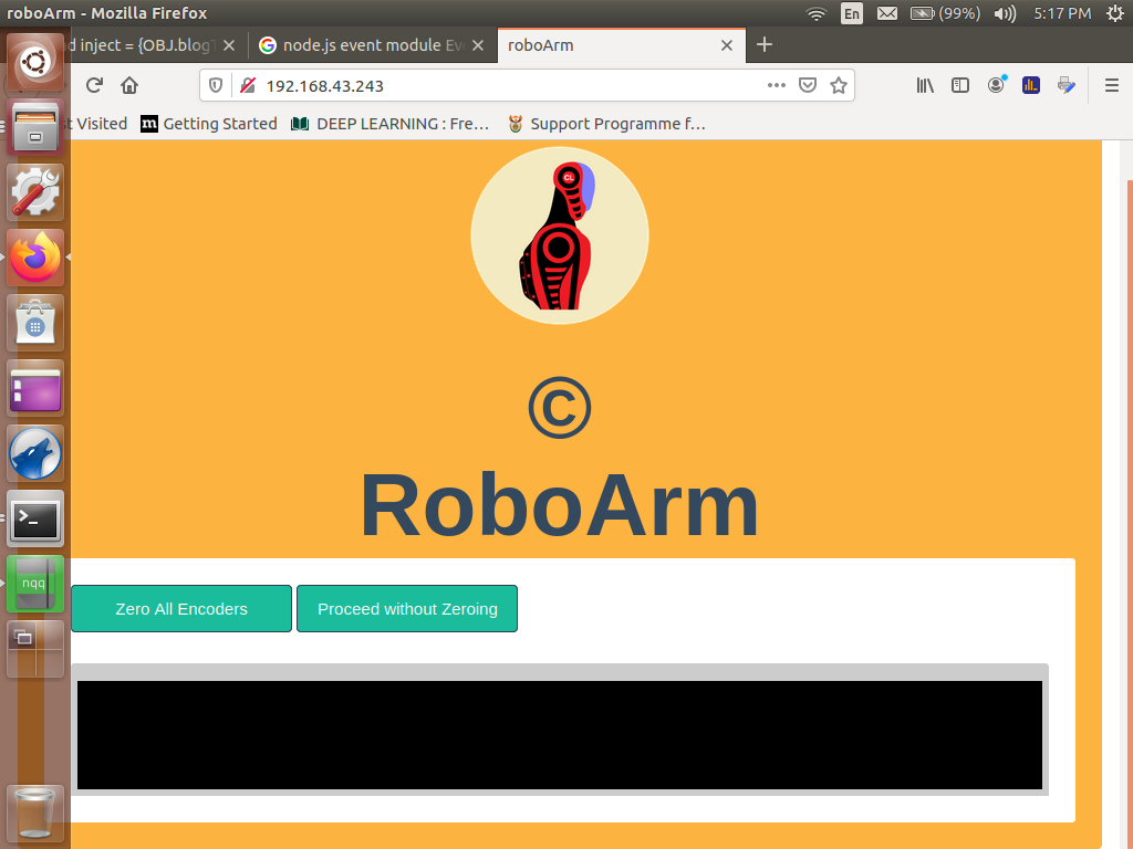
Slide-4
The structure of the front-end files is very similar to that of the NodeMCU project. Within the "pg" folder, we have got the "index.html" file, and the four directories "css", "font-awesome" "fonts", "img" and "js". Here is the "index.html" code for the page.
index.html
<!DOCTYPE html>

<html lang="en">

	<head>
		<title>roboArm</title>

		<meta charset="utf-8">
		<meta name="viewport" content="width=device-width, initial-scale=1">

		<!-- Custom Google Web Font -->
		<link href="font-awesome/css/font-awesome.css" rel="stylesheet">

		<!-- Bootstrap core CSS -->
		<link href="css/bootstrap.css" rel="stylesheet">

		<link href="css/style.css" rel="stylesheet">
		<link href="css/settings.css" rel="stylesheet">

		<script src = "js/ws.js"></script>
	</head>

	<body lang="en" onresize = "reSize()">


		<div class = "msg mode mod_null" id = "msg" style = "display: none;">

			<p> </p>

			<div class = "col-md-12">
				<span id = "colorChooser" class = "red">
					<h4 id = "msgTxt"></h4>
				</span>
			</div>

			<button class = "btn btn-primary to-the-right"
				onclick = "okButton()" ontouch = "okButton()">OK</button>
		</div>

		<div class = "msg mode mod_null" id = "msg_dialog" style = "display: none;">

			<p> </p>

			<div class = "col-md-12">
				<span class = "blue"><h4 id = "msgInfo"></h4></span>
			</div>

			<button class = "btn btn-primary to-the-right"
				onclick = "yesButton()" ontouch = "yesButton()">Yes</button>
			<button class = "btn btn-primary to-the-right"
				onclick = "noButton()" ontouch = "noButton()">No</button>
		</div>


		<div class = "splash mode mod_zeroing mod_zero-complete mod_untrip"
			id = "splash" style = "display: inline;">

			<div class = "col-md-12">

				<div class = "col-md-6 col-md-offset-3">
					<img src="img/logo.png" height = "162px;"
						style = "margin-left: calc(50% - 81px)"/><br>
				</div>

				<div class = "col-md-6 col-md-offset-3">
					<h1 class = "scalable" style = "text-align: center;">
						© RoboArm
					</h1>
				</div>
			</div>

			<div class = "col-md-12 white-background">

				<button class = "btn btn-primary mode mod_zeroing mod_untrip"
					onclick = "requestZeroing()" ontouch = "requestZeroing()"
					id = "zero">Zero All Encoders</button>

				<button class = "btn btn-primary mode mod_untrip"
					onclick = "hideSplash()" ontouch = "hideSplash()"
					id = "noZero">Proceed without Zeroing</button>

				<img class = "mode mod_zeroing" src = "img/45.gif"
					alt = "progress... gif" id = "progressGif" style = "display: none;"/>

				<h3 class = "mode mod_zero-complete"
					style = "display: none;">Zeroing complete</h3>

				<div class = "col-md-12 console-output">
					<p id = "console_output2"></p>
					<p id = "console_output1"></p>
				</div>
			</div>
		</div>


		<div class = "splash mode mod_naming-seq" id = "dialog"
			style = "display: none;">

			<div class = "col-md-12">

				<div class = "col-md-6 col-md-offset-3">
					<img src="img/logo.png" height = "162px;"
						style = "margin-left: calc(50% - 81px)"/><br>
				</div>
			</div>

			<p> </p>

			<div class = "col-md-4 col-md-offset-4"
				style = "background-color: #fff; padding: 24px;">

				<p>Name your sequence:</p>

				<input class="form-control" type = "text" id = "seqName"
					name = "seqName" placeholder = "Enter name of Sequence"/>

				<p> </p>

				<button class = "btn btn-primary" onclick = "cancelSeqCreation()"
					ontouch = "cancelSeqCreation()">Cancel</button>

				<button class = "btn btn-primary to-the-right" onclick = "submitName()"
					ontouch = "submitName()">Next ></button>
			</div>
		</div>


		<div class = "splash mode mod_select-seq"
			id = "seqPage" style = "display: none;">

			<button class = "close-btn" onclick = "closePg('manual')"
				ontouch = "closePg('manual')">Close</button>

			<div class = "col-md-12">
				<h2 class = "scalable">©RoboArm<img src="img/logo.png"
					height = "120px;" style = "margin-left: 40px;"/></h2>
			</div>

			<div class = "col-md-12 btn-pannel" id = "seqDisplay">

				<button class = "btn btn-primary big" onclick = "newCreateSeqProcess()"
					ontouch = "newCreateSeqProcess()">
					<li class = "fa fa-3x fa-plus-square"></li>
					<li>New Sequence</li>
				</button>

				<button class = "btn btn-primary big" onclick = "requestZeroing()"
					ontouch = "requestZeroing()">
					<li class = "fa fa-3x fa-cogs"></li>
					<li> </li>
					<li>Zero Encoders</li>
				</button>

				<button class = "btn btn-primary big" onclick = "goHome()"
					ontouch = "goHome()">
					<li class = "fa fa-3x fa-cogs"></li>
					<li> </li>
					<li>Go Home</li>
				</button>
			</div>
		</div>


		<div class = "splash mode mod_consider-seq"
			id = "considerSeq" style = "display: none;">

			<button class = "close-btn" onclick = "closePg('select-seq')"
				ontouch = "closePg('select-seq')">Close</button>

			<div class = "col-md-12">
				<h2 class = "scalable">©RoboArm<img src="img/logo.png"
					height = "120px;" style = "margin-left: 40px;"/></h2>
			</div>

			<div class = "col-md-12">
				<h4 class = "scalable">
					Sequence: <span id = "seqNamePlaceHolder"></span>
				</h4>
			</div>

			<div class = "col-md-12 btn-pannel" id = "seqEditPannel">

				<button class = "btn btn-primary big blu" onclick = "playSeq()"
					ontouch = "playSeq()">
					<li class = "fa fa-3x fa-play"></li>
					<li> </li>
					<li>Play</li>
				</button>

				<button class = "btn btn-primary big blu" onclick = "editThisSeq()"
					ontouch = "editThisSeq()">
					<li class = "fa fa-3x fa-wrench"></li>
					<li> </li>
					<li>Edit</li>
				</button>

				<button class = "btn btn-primary big blu"
					onclick = "deleteSeq()" ontouch = "deleteSeq()">
					<li class = "fa fa-3x fa-trash-o"></li>
					<li> </li>
					<li>Delete</li>
				</button>
			</div>
		</div>


		<div class = "mode mod_manual mod_creating-seq"
			id = "ctr_pannel" style = "display: none;">

			<div class = "col-md-2 side-bar">

				<img src="img/logo.png" height = "162px;"/>

				<div class = "col-md-12">
					<p style = "text-align: center;"> © 2020 RoboArm.</p>
				</div>

				<div class = "col-md-12 mode mod_manual" style = "display: inline;">
					<button class = "btn btn-primary" onclick = "gotoSeqPage()"
						ontouch = "gotoSeqPage()">Run Sequence</button>
				</div>

				<div class = "col-md-12 mode mod_creating-seq" style = "display: none;">

					<button class = "btn btn-primary seq" onclick = "abortCreation()"
						ontouch = "abortCreation()">Abort Creation</button>

					<button class = "btn btn-primary seq" onclick = "saveSeq()"
						ontouch = "saveSeq()">Save Sequence</button>
				</div>
			</div>

			<div class = "col-md-10">

				<div class = "col-md-12">

					<h2 class = "mode mod_manual">Manual Controls</h2>

					<p id = "disp" style = "color: #000;">Srv:</p>

					<div class = "col-md-4">

						<div class = "sect">

							<h4>Hand</h4>

							<p>No-encoder-val-for-hand</p>

							<div class = "unit-line">
								<div class="hlf">
									<input class="form-control" type = "text" id = "m5dr1"
										name = "m5dr1" value = "220"/>
								</div>

								<div class="hlf">
									<button class = "btn btn-primary" onmousedown = "cmd('m5 d1')"
									ontouchstart = "cmd('m5 d1')" onmouseup = "cmd('m5 stop')"
									ontouchend = "cmd('m5 stop')" id = "btn_m5d1">Release</button>
								</div>
							</div>

							<div class = "unit-line">
								<div class="hlf">
									<input class = "form-control" type = "text" id = "m5dr2"
									name = "m5dr2" value = "180"/>
								</div>

								<div class="hlf">
									<button class = "btn btn-primary" onmousedown = "cmd('m5 d2')"
									ontouchstart = "cmd('m5 d2')" onmouseup = "cmd('m5 stop')"
									ontouchend = "cmd('m5 stop')" id = "btn_m5d2">Grab</button>
								</div>
							</div>

							<br style = "clear: both;">
						</div>
					</div>

					<div class = "col-md-4">

						<div class = "sect">

							<h4>Wrist</h4>

							<p id = "disp4" style = "color: #000;">
								Wriste-encoder-val
							</p>

							<div class = "unit-line">
								<div class="hlf">
									<input class="form-control" type = "text"
										id = "m4dr1" name = "m4dr1" value = "45"/>
								</div>

								<div class="hlf">
									<button class = "btn btn-primary" onmousedown = "cmd('m4 d1')"
										ontouchstart = "cmd('m4 d1')" onmouseup = "cmd('m4 stop')"
										ontouchend = "cmd('m4 stop')" id = "btn_m4d1">Left</button>
								</div>
							</div>

							<div class = "unit-line">
								<div class="hlf">
									<input class = "form-control" type = "text"
										id = "m4dr2" name = "m4dr2" value = "45"/>
								</div>

								<div class="hlf">
									<button class = "btn btn-primary" onmousedown = "cmd('m4 d2')"
										ontouchstart = "cmd('m4 d2')" onmouseup = "cmd('m4 stop')"
										ontouchend = "cmd('m4 stop')" id = "btn_m4d2">Right</button>
								</div>
							</div>

							<br style = "clear: both;">
						</div>
					</div>

					<div class = "col-md-4">

						<div class = "sect">

							<h4>Elbow</h4>

							<p id = "disp3" style = "color: #000;">
								Elbow-encoder-val
							</p>

							<div class = "unit-line">
								<div class="hlf">
									<input class="form-control" type = "text"
										id = "m3dr1" name = "m3dr1" value = "180"/>
								</div>

								<div class="hlf">
									<button class = "btn btn-primary" onmousedown = "cmd('m3 d1')"
										ontouchstart = "cmd('m3 d1')" onmouseup = "cmd('m3 stop')"
										ontouchend = "cmd('m3 stop')" id = "btn_m3d1">Up</button>
								</div>
							</div>

							<div class = "unit-line">
								<div class="hlf">
									<input class = "form-control" type = "text"
										id = "m3dr2" name = "m3dr2" value = "170"/>
								</div>

								<div class="hlf">
									<button class = "btn btn-primary" onmousedown = "cmd('m3 d2')"
										ontouchstart = "cmd('m3 d2')" onmouseup = "cmd('m3 stop')"
										ontouchend = "cmd('m3 stop')" id = "btn_m3d2">Down</button>
								</div>
							</div>

							<br style = "clear: both;">
						</div>
					</div>

					<div class = "col-md-4">

						<div class = "sect">

							<h4>Arm</h4>

							<p id = "disp2" style = "color: #000;">
								Arm-encoder-val
							</p>

							<div class = "unit-line">
								<div class="hlf">
									<input class="form-control" type = "text"
										id = "m2dr1" name = "m2dr1" value = "95"/>
								</div>

								<div class="hlf">
									<button class = "btn btn-primary" onmousedown = "cmd('m2 d1')"
									ontouchstart = "cmd('m2 d1')" onmouseup = "cmd('m2 stop')"
									ontouchend = "cmd('m2 stop')" id = "btn_m2d1">Up</button>
								</div>
							</div>

							<div class = "unit-line">
								<div class="hlf">
									<input class = "form-control" type = "text"
										id = "m2dr2" name = "m2dr2" value = "40"/>
								</div>

								<div class="hlf">
									<button class = "btn btn-primary" onmousedown = "cmd('m2 d2')"
										ontouchstart = "cmd('m2 d2')" onmouseup = "cmd('m2 stop')"
										ontouchend = "cmd('m2 stop')" id = "btn_m2d2">Down</button>
								</div>
							</div>

							<br style = "clear: both;">
						</div>
					</div>

					<div class = "col-md-4">

						<div class = "sect">

							<h4>Shoulder</h4>

							<p id = "disp1" style = "color: #000;">Shoulder-encoder-val</p>

							<div class = "unit-line">
								<div class="hlf">
									<input class="form-control" type = "text"
										id = "m1dr1" name = "m1dr1" value = "60"/>
								</div>

								<div class="hlf">
									<button class = "btn btn-primary" onmousedown = "cmd('m1 d1')"
										ontouchstart = "cmd('m1 d1')" onmouseup = "cmd('m1 stop')"
										ontouchend = "cmd('m1 stop')" id = "btn_m1d1">Right</button>
								</div>
							</div>

							<div class = "unit-line">
								<div class="hlf">
									<input class = "form-control" type = "text"
										id = "m1dr2" name = "m1dr2" value = "60"/>
								</div>

								<div class="hlf">
									<button class = "btn btn-primary" onmousedown = "cmd('m1 d2')"
										ontouchstart = "cmd('m1 d2')" onmouseup = "cmd('m1 stop')"
										ontouchend = "cmd('m1 stop')" id = "btn_m1d2">Left</button>
								</div>
							</div>

							<br style = "clear: both;">
						</div>
					</div>

					<div class = "col-md-4 mode mod_creating-seq" style = "display: none;">

						<div class = "sect different-sect">

							<h4 id = "coordinadeName">coordinate-name</h4>

							<p style = "color: #000;">

								(<span id = "x1">0</span>,
								<span id = "x2">0</span>,
								<span id = "x3">0</span>,
								<span id = "x4">0</span>)
								  Index:

								<select id = "arr_index" name = "arr_index">
									<option value = "0">0</option>
								</select>
							</p>

							<select class="sp-select" id = "afterAction" name = "afterAction">
								<option value = "10">Hand action: Open</option>
								<option value = "20">Hand action: Close</option>
							</select>

							<div style = "margin-top: 6px;">

								<button class = "btn btn-primary" onclick = "addThisCoordinate()"
									ontouch = "addThisCoordinate()" id = "add" name = "add">
									Add +
								<button>

								<button class = "btn btn-primary" onclick = "hiddenZero()"
									ontouch = "hiddenZero()" id = "btnZero" name = "btnZero">Zero</button>

								<button class = "btn btn-primary to-the-right" onclick = "editSeq()"
									ontouch = "editSeq()" id = "finish" name = "finish">Edit</button>
							</div>

							<span style = "clear: both;"></span>
						</div>
					</div>
				</div>

				<h1> </h1>
			</div>
		</div>

		<!-- JavaScript -->
		<script src="js/bootstrap.js"></script>
		<script src = "js/index.js"></script>
	</body>
</html>
Sketch-14
Despite a wide variaty of display items that our project's GUI collection comprises of, there is only just one HTML script that accounts for them. The scheme that I have deviced to bring this about is to have an arrangment where targeted elements of our Visual HTML code are programatically hidable and displayable by means of a JavaScript code that selects which to show and which to hide based on a form of classification an element belongs to.
The classification system works like this: every element that must be put under the control of the hidding and displaying JavaScript code should have among its other class attribute's listed items the item "mode" and then a mode name written in the form "mod_xxxx" or the name "mod_null" in the case of an element without a special indentification mode-name.
In this way, the JavaScript code can declare which mode should be set on display while the rest are hidden by assigning the element with the targeted mode-name the inline style attribute 'style = "display: inline;"' while the rest of the elements with the "mode" class attribute indentification are set to the condition defined by the inline style attribute 'style = "display: none;"'.
The HTML code shown in Sketch-14 is such that the body is divided into 7 div elements all assigned to different mode classifications. Some of the elements may share a mode-name (see Lines 55 and 85). This only serves to indicate that when the mode-name that they share is called upon to manifest itself, all the elements that share that name will all appear at the same time.
On load, the code in Sketch-14 displays the section defined from Line 55 to Line 93 because the div element that contains it is assigned the inline style attribute that displays the element. Visually, this may be understood to mean that the first thing that a user is greeted with when they access the robot's UI page is the screen that asks him if he desires to zero the robot or to proceed without doing so.
Apart from third party resources such as the Bootstrap's CSS script and it JavaScript files, font files and font-awesome files etc, here is a list of the other dependency files for the HTML script. I have elected to let you be the one to decipher how they corelate to the rest of the code discussed thus far:
The "forRaspberryPi/pg/js/index.js" file
var seqName = "",
	thisMode = "mod_untrip",
	dialogRef = "";


function reSize() {

	var disp = "width = " + window.innerWidth + ",
		height = " + window.innerHeight;

	document.getElementById('disp').innerHTML = disp;
}


function gotoSeqPage() {

	chageModeTo('mod_select-seq');
	ws.send("readSequences()");
	var el = document.getElementById('arr_index');
	el.innerHTML = '<option value = "0">0</option>';
}


function cancelSeqCreation() { gotoSeqPage(); }


function submitName() {

	var el = document.getElementById('seqName');
	if (el.value != (null | undefined)) {

		seqName = el.value;
		ws.send("createSeq(" + seqName + ")");
	}

	else {

		var msg = 'You need to furnish a "Name" in ' +
			'order to proceed with this process.';

		alert(msg);
	}
}


function newCreateSeqProcess() {
	chageModeTo('mod_naming-seq');
}


function abortCreation() {

	ws.send("abortCreation(" + seqName + ")");
	seqName = "";
}

// Event handler for the button used for closing some of the
// splash modes' screens.
function closePg(pg) {

	if (pg == "manual") { chageModeTo('mod_manual'); }
	else if (pg == "select-seq") { gotoSeqPage(); }

	else if (pg == "consider-seq") {
		chageModeTo('mod_consider-seq');
	}

	else if (pg == "untrip") { chageModeTo('mod_untrip'); }
}


function chageModeTo(mode) {

	oldMode = thisMode;
	thisMode = mode;

	var allModes = document.getElementsByClassName('mode');
	var selMode = document.getElementsByClassName(mode);

	for (var i = 0; i < allModes.length; i++) {
		allModes[i].setAttribute('style', "display: none;");
	}

	for (var j = 0; j < selMode.length; j++) {
		selMode[j].setAttribute('style', "display: inline;");
	}
}

// Function called whenever a user submits a coordinate
// to be updated in an automated sequence being created.
function addThisCoordinate() {

	var coordinateName = document.getElementById('coordinateName');
	var x5 = document.getElementById('afterAction').value;

	var x1 = document.getElementById('x1').innerHTML;
	var x2 = document.getElementById('x2').innerHTML;
	var x3 = document.getElementById('x3').innerHTML;
	var x4 = document.getElementById('x4').innerHTML;

	var msg =

		"editSeq(" + seqName + "|" + x1 + "," + x2 + "," + x3 +
		"," + x4 + "," + x5 + "|" +
		document.getElementById('arr_index').value + ")"

	ws.send(msg);
}


function saveSeq() {

	gotoSeqPage();
	seqName = "";
}

function considerSeq(name) {

	seqName = name;
	var el = document.getElementById('seqNamePlaceHolder');
	el.innerHTML = name;
	chageModeTo('mod_consider-seq');
}

// For the zeroing process called within the visuals of a create
// sequence display.
function hiddenZero() {

	enableDisable("disable", document.getElementById('btnZero'));
	ws.send("zero-encoders");
}

function deleteSeq() {

	var msgBox = document.getElementById('msg_dialog');
	var msgBoxClass = msgBox.getAttribute("class");

	dialogRef = "delete-seq";

	document.getElementById('msgInfo').innerHTML =

		'Are you sure that you want to delete the "' +
		seqName + '" sequence?';

	msgBox.setAttribute("class", msgBoxClass.replace("mod_null", thisMode));
	chageModeTo(thisMode);
}

function requestSystemEnable() {

	var msgBox = document.getElementById('msg_dialog');
	var msgBoxClass = msgBox.getAttribute("class");

	dialogRef = "request-system-enable";

	document.getElementById('msgInfo').innerHTML =

		'The system has been tripped. Do you wish to enable it?';

	msgBox.setAttribute("class", msgBoxClass.replace("mod_null", thisMode));
	chageModeTo(thisMode);
}


function playSeq() { ws.send('runSeq(' + seqName + ')'); }

// Code for this function is not yet created on the server side.
function goHome() { ws.send('goHome()'); }

// For the dialogBox.
function yesButton() {

	if (dialogRef == "delete-seq") {

		ws.send("abortCreation(" + seqName + ")");
		seqName = "";
		dialogRef = "";
		noButton();
	}

	else if (dialogRef == "request-system-enable") {

		ws.send("request-system-enable");
		dialogRef = "";
		noButton();
	}
}

// For the dialogBox.
function noButton() {

	var msgBox = document.getElementById('msg_dialog');
	var msgBoxClass = msgBox.getAttribute("class");

	msgBox.setAttribute("class", msgBoxClass.replace(thisMode, "mod_null"));

	if (dialogRef == "delete-seq") { closePg('consider-seq'); }
	else if (dialogRef == "request-system-enable") { closePg('untrip'); }

	dialogRef = "";
}
Sketch-15
The "forRaspberryPi/pg/js/ws.js" file
//
// Replace with own IP address
var ws = new WebSocket("ws://000.000.000.000");

// For the zeroing process display.	There are 2 lines for
// displaying  called "consoleOutput1" and "consoleOutput2".
var consoleOutput1, consoleOutput2;

// Also for the zeroing process display. There are 2 lines for
// displaying referenced 1 and 2.
var oldRef = -1;

var txt = "";	// Also for the zeroing process display.
var isItFirstTime = true;	// Also for the zeroing process display.

var seqDisplayMinContent =

// The "Create New Sequence" button for the select sequence mode
'<button class = "btn btn-primary big" ' +
	'onclick = "newCreateSeqProcess()" ontouch = "newCreateSeqProcess()">' +
	'<li class = "fa fa-3x fa-plus-square"></li>' +
	'<li>New Sequence</li>' +
'</button>' +

// The "Zero Encoders" button for the select sequence mode
'<button class = "btn btn-primary big" ' +
	'onclick = "requestZeroing()" ontouch = "requestZeroing()">' +
	'<li class = "fa fa-3x fa-cogs"></li>' +
	'<li> </li>' +
	'<li>Zero Encoders</li>' +
'</button>';

ws.onopen = function(e) {

	var el = document.getElementById('disp');
	el.innerHTML = 'Connection to server opened';
}

ws.onmessage = function(e) {

	var data = e.data;

	// For determining which button for a specific motor's
	// specific direction of rotation that needs to be
	// disabled.
	var dir_ls = {
		m1: "d2", m2: "d1", m3: "d2", m4: "d1", m5: "d1"
	};

	if (data.indexOf('Show_message:') != -1) {

		var errMsg = data.substring(14);
		displayMessages(errMsg, "error");
	}

	else if (data.indexOf('Feedback>') != -1) {

		var dataArr = data.split(">");
		var feedbackMsg = dataArr[1];

		if (feedbackMsg == "file-saved") {

			chageModeTo('mod_creating-seq');
			var el = document.getElementById('coordinadeName');
			el.innerHTML = "Seq: " + seqName;
		}

		else if (feedbackMsg == "file-deleted") { gotoSeqPage(); }

		// Test for the format: ["xx...", "xx...",...] where "xx..."
		// means any string of charectors of type "\w". This is a
		// list of all sequences saved in the "sequnence.seq" file.
		else if (/^\[("[\w]+"(,){0,1})*\]$/.test(feedbackMsg)) {

			var names = JSON.parse(feedbackMsg);
			var dynamicContent = "";
			var staticAttributes =

				'class = "btn btn-primary big" ' =
				'style ="background-color: #00A4EF !important;"';

			// Mass-produce buttons to be diplaced on the select
			// sequence mode over and above the create new sequence
			// button and the zero encoders button.
			for (var i = 0; i < names.length; i++) {

				dynamicContent +=

				'<button ' + staticAttributes +
					' onclick = "considerSeq(\'' + names[i] + '\')" ' +
					'ontouch = "considerSeq(\'' + names[i] + '\')">' +
					'<li class = "fa fa-3x fa-cogs"></li>' +
					'<li> </li>' +
					'<li>' + names[i] + '</li>'+
				'</button>';

				if (i == names.length - 1) {

					var el = document.getElementById('seqDisplay');
					el.innerHTML = seqDisplayMinContent + dynamicContent;
				}
			}

			if (names.length == 0) {

				var el = document.getElementById('seqDisplay');
				el.innerHTML = seqDisplayMinContent + dynamicContent;
			}
		}

		else { displayMessages(feedbackMsg, "alert"); }
	}

	// Useful when creating an automated sequence.
	// A user may choose at which point along the
	// the sequence's array indices he/she chooses
	// to insert his/her coordinate.
	else if (data.indexOf('Array-Size:') != -1) {

		var size = Number(data.split(":")[1]);
		var options = "";

		for (var i = 0; i < size + 1; i++) {

			options += '<option value = "' + i +
				'">' + i + '</option>';
		}

		document.getElementById('arr_index').innerHTML = options;
		document.getElementById('arr_index').value = String(size);
	}

	// For the zero encoders process's pseudo console.
	else if (data.indexOf('display=') != -1) {

		var el = document.getElementById('disp');
		el.innerHTML = '  ' + data;
		var dataArr = data.split(' ');
		var display = dataArr[0];
		var message = dataArr[1];

		var dispNo = Number(display.split('=')[1]);

		var el1 = document.getElementById('disp' + dispNo);
		var el2 = document.getElementById('x' + dispNo);
		el1.innerHTML = '  ' + message;
		el2.innerHTML = message.split(':')[1];

		if (oldRef != dispNo) {

			txt = (isItFirstTime ? consoleOutput2.innerHTML :
				consoleOutput2.innerHTML + ", ");

			isItFirstTime = false;
			oldRef = dispNo;
		}

		consoleOutput2.innerHTML = txt + message;
	}

	// Code used for disabling a button when motoin in set
	// direction is no longer desired.
	else if(data.indexOf('{"sw":') != -1) {

		var obj = JSON.parse(data);
		var str = 'btn_' + obj.motor + dir_ls[obj.motor];
		var butt = document.getElementById(str);

		if (obj.vl == 1) { enableDisable("disable", butt); }
		else { enableDisable("enable", butt); }

		consoleOutput1.innerHTML =
			(data.replace('{', '')).replace('}', '');
	}

	else if (data.indexOf('hide-splash') != -1) {

		setTimeout(() => { hideSplash(); }, 1800);
		chageModeTo('mod_zero-complete');
		consoleOutput1.innerHTML = "";
		consoleOutput2.innerHTML = "";
		isItFirstTime = true;
	}

	else if (data.indexOf('hidden-zeroing-complete') != -1) {
		enableDisable("enable", document.getElementById('btnZero'));
	}

	else if (data.indexOf('msg>system-is-tripped') != -1) {
		requestSystemEnable(); tripStatus = true;
	}

	else if (data.indexOf('msg>system-is-enabled') != -1) {
		displayMessages("The system has been enabled!", "alert");
		tripStatus = false;
	}

	else {

		document.getElementById('disp').innerHTML = data;

		if (data.indexOf('Zeroing') != -1) {
			consoleOutput1.innerHTML =
			(data.replace('{', '')).replace('}', '').replace(':"', ': "');
		}
	}
}

ws.onclose = function(e) {

	document.getElementById('disp').innerHTML =
		"Connection closed";
}


function cmd(nm) {

	var duty = (nm.indexOf('stop') != -1 ? 0 :
		document.getElementById(nm.replace(' d', 'dr')).value);

	ws.send("motor-cmd=>" + nm + ' ' + duty);
}

function requestZeroing() {

	chageModeTo('mod_zeroing');
	enableDisable("disable", document.getElementById('zero'));

	consoleOutput1 = document.getElementById('console_output1');
	consoleOutput2 = document.getElementById('console_output2');
	consoleOutput1.innerHTML = 'Encoder zeroing has commenced';
	setTimeout(() => { ws.send("zero-all-encoders");  }, 400);
}

function hideSplash() { chageModeTo('mod_manual'); }

function enableDisable(cmd, btn) {

	if (cmd == "disable") {

		var str = "  \u26d4";
		btn.setAttribute('disabled', "true");
		btn.setAttribute('style', "background-color: #D90000;");
		btn.innerHTML +=
			(btn.innerHTML.indexOf(str) == -1 ? str : "");
	}

	else if (cmd == "enable") {

		var lbl = btn.innerHTML;

		btn.removeAttribute('disabled');
		btn.removeAttribute('style');
		btn.innerHTML = lbl.replace('  \u26d4', '') ;
	}
}

// For the OK button on the system's messageBox
function okButton() {

	var msgBox = document.getElementById('msg');
	var msgBoxClass = msgBox.getAttribute("class");

	msgBox.setAttribute("class",
		msgBoxClass.replace(thisMode, "mod_null"));

	chageModeTo(thisMode);
}

// For the system's dialogBox
function displayMessages(msg, type) {

	var msgBox = document.getElementById('msg');
	var msgBoxClass = msgBox.getAttribute("class");

	document.getElementById('msgTxt').innerHTML = msg;

	msgBox.setAttribute("class",
		msgBoxClass.replace("mod_null", thisMode));

	if (type == "error") {

		var el = document.getElementById('colorChooser');
		el.setAttribute("class", "red");
	}

	else if (type == "alert") {

		var el = document.getElementById('colorChooser');
		el.setAttribute("class", "green");
	}

	chageModeTo(thisMode);
}
Sketch-16
The "forRaspberryPi/pg/css/settings.css" file
body, html {

	height: 100%;
	width: 100%;
	overflow-x:hidden;
}

.side-bar {

	background-color: #C39FBB;
	height: calc(100vh + 210px);
	display: block;
	padding: 24px 0;
	color: white;
	border-right: 5px solid #782175;
}

.side-bar img { margin-left: calc(50% - 81px) }

.sect {

	background-color: #D9D9D9;
	padding: 24px 12px;
	border-radius: 3px;
	margin-top: 24px;
	margin-bottom: 24px;
}

.different-sect { background-color: #FDB33F; }

.sect .btn, .sect input { margin-bottom: 4px; }

.unit-line .col-md-6 { padding-left: 0; }

.unit-line .hlf {

	width: 50%;
	float: left;
	padding-right: 6px;
}

.unit-line button { width: 100%; }

.splash {

	position: absolute;
	left: 16px;
	top: 16px;
	width: calc(100% - 32px);
	min-height: calc(100vh - 32px);
	background-color: #FDB33F;
	padding: 24px;
	border-radius: 4px;
	z-index: 999 !important;
	margin-bottom: 50px;
}

.console-output {

	background-color: #000;
	border: 6px solid #ccc;
	border-top: 16px solid #ccc;
	padding: 8px;
	height: 120px;
	margin-top: 20px;
	color: #40E940;
	overflow: auto;
	border-top-left-radius: 3px;
	border-top-right-radius: 3px;
}

.white-background {

	background-color: #fff;
	padding: 24px;
	border-radius: 3px;
}

.white-background h3 { color: green !important;  }

.white-background button {

	margin-bottom: 8px;
	width: 200px;
}

#console-output1, #console-output2 { text-align: left !important; }

#progressGif { margin-left: calc(50% - 24em); }

.sp-select {

	border: 2px solid #48C9B0;
	border-radius: 6px;
	padding: 6px;
	width: 100%;
}

.chk { margin: 8px 0; }

.big {

	width: 140px;
	height: 120px;
	float: left;
	margin-right: 24px;
	margin-bottom: 24px;
}

.blu { background-color: #00A4EF !important; }

.btn-pannel {

	padding: 24px;
	margin: 12px;
	border-top: 2px solid #fff;
}

.close-btn {

	float: right;
	border-radius: 4px;
}

.seq {

	background-color: #FDB33F;
	color: #000;
	width: 140px;
	margin-bottom: 8px;
}

.seq:hover {

	background-color: #EDB33F;
	color: #000;
	border: 1px solid #fff;
}

.to-the-right {

	float: right;
	margin-left: 8px;
}

.msg {

	position: absolute;
	left: calc(50% - 156px);
	top: calc(50vh - 90px);
	width: 460px;
	min-height: 220px;
	background-color: #fff;
	padding: 12px;
	border-radius: 4px;
	border: 2px solid #555;
	z-index: 9999 !important;
	opacity: 0.92;
}

.red { color: red; }

.green { color: green; }

.blue { color: blue; }


@media (max-width: 992px) {

	.side-bar {

		height: 310px !important;
		border-right: none;
	}

	.console-output { height: 180px; text-align: left !important; }

	#progressGif { margin-left: 12px; }

	.scalable { font-size: 36px; }

	.msg {

		position: fixed;
		left: 36px;
		top: auto;
		bottom: 120px;
		width: calc(100% - 72px);
	}
}
Sketch-17
At this point, compile everything and then try to run your "supervisor.js" script first on your Raspberry Pi computer and then run the "wsServer.js" afterwards. When you connect to the the server (the Raspberry Pi) using a mobile phone for example (I recommend a wide screen tablet), a pop-up dialogBox message will appear and inform you that the system has been tripped and then ask you if you wish to enable it. You will need to do so before the robot can work.
Finaly, consider how the robot works by watching the videos below. I wish you every success in your project but please write to me should you encounter some serious challenges. All the best!
Video-2 [Automated Zero-position sequence]
Video-3 [A more elaborate automated sequence]
Video-4 [Hardware overview]